Application scope
- PET small bottle water lines
- PET hot-fill beverage lines
- PET carbonated soft drink lines

PET Blow Molding and Bottle Handling
PET air conveying systems utilize neck-guidance rails to support lightweight empty bottles, using controlled directional airflow within enclosed ducts to transport containers continuously from standalone blow molding machines to downstream filling equipment.
Project fit snapshot
Suitability depends on the product, container, output, hygienic route and connected equipment. Conditions outside the published scope require engineering review.
Technical content: fourth editionProject records shown below are project-specific references, not standard specifications.
PET air conveying systems utilize neck-guidance rails to support lightweight empty bottles, using controlled directional airflow within enclosed ducts to transport containers continuously from standalone blow molding machines to downstream filling equipment.
Lightweight PET containers require stable pneumatic transfer to maintain high-speed delivery without applying mechanical gripping pressure to delicate container walls. Proper airflow management ensures consistent spacing and prevents surface damage during inter-machine transfer.
The air conveying system suspends empty bottles by their neck support rings and propels them using controlled airflow. The system must simultaneously govern bottle suspension, airflow direction, conveying velocity, and accumulation pressure.
Conveying capacity must be matched to bottle geometry, weight, and target line speed. Critical sections such as curves, elevation changes, long-distance runs, and machine inlets require zoned guide rails, partitioned airflow volumes, and sensor monitoring to maintain stable bottle flow without relying solely on high blower power.
Neck Support Rails: Carries empty containers via support rings, with rail gaps adjustable for varying neck finishes and changeover ranges.
Ducted Blowers: Supplies zoned airflow along transport paths, curves, and speed segments to prevent localized over-pressurization.
Bottle Body Guidance: Controls container swing and cornering posture to prevent bottle-to-bottle collisions.
Sectional Detection: Incorporates presence and congestion sensors at machine inlets, curves, and buffer zones.
Equipment Interfacing: Synchronizes height, pitch, and speed between blow molder discharge and filler infeed.
Scroll horizontally to see all table columns.
| Component | Function |
|---|---|
| Neck Guide Rails | Serves as the load-bearing baseline using bottle neck support rings, eliminating body clamping |
| Ducts and Blowers | Generates directional airflow along the conveying path to overcome resistance and propel containers |
| Curves, Elevation, and Merging Sections | Executes spatial path transitions required by plant layout configurations |
| Guidance and Adjustment Components | Maintains bottle flow stability across varying neck and body dimensions |
| Detection and Sectional Controls | Identifies missing bottles, full lines, and congestion, regulating blowers and upstream output |
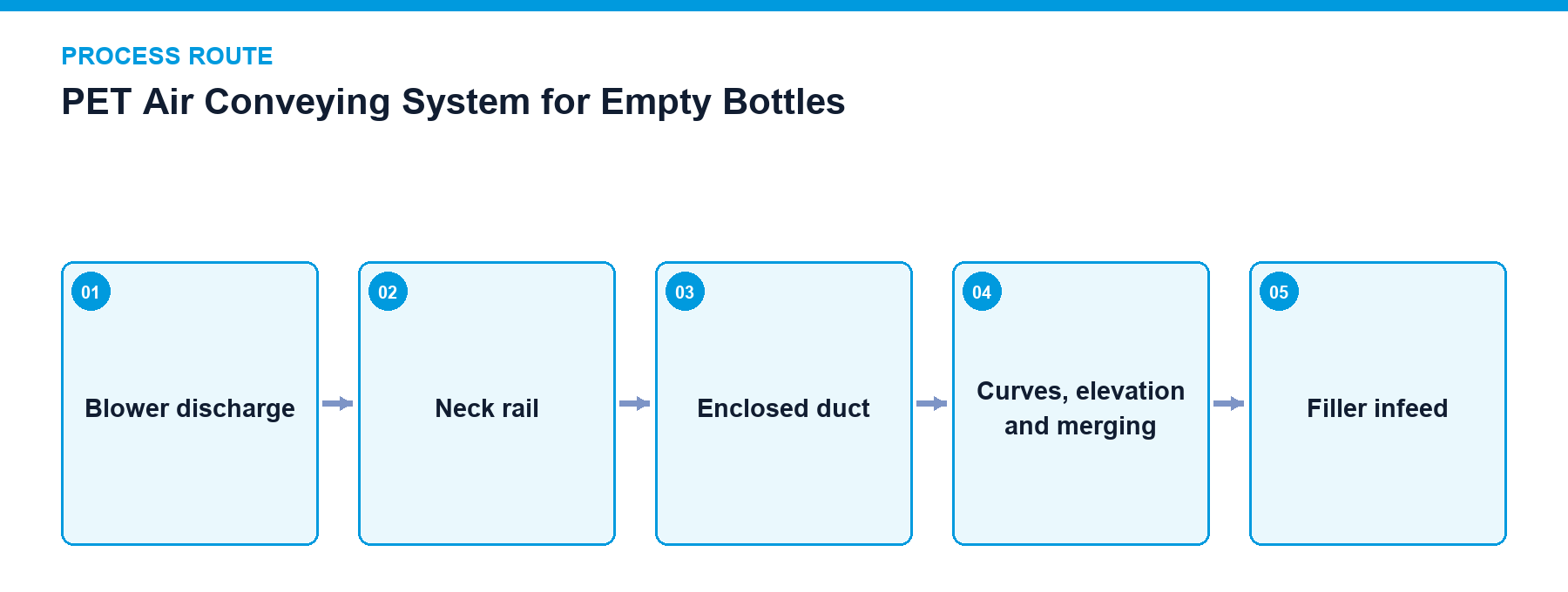
Inlet Reception: Receives empty bottles discharged from the blow molding machine onto neck guide rails.
Pneumatic Transport: Propels containers through enclosed ducts via partitioned blower airflow.
Path Transition: Guides bottles smoothly through curves, elevation changes, and merging junctions.
Congestion Management: Automatically suppresses upstream supply when filling machine accumulation reaches capacity limits.
Interlock Monitoring: Coordinates operational states between blow molders, blowers, and filling equipment.
Filling machine inlet full-line suppression of upstream supply
Sectional blower start/stop control
Missing bottle and congestion detection
Blow molding and filling equipment status exchange
Access door and blower safety interlocks
Keep blower inlet filters, internal duct surfaces, and neck support rails clean.
Periodically inspect neck contact components for wear to prevent jamming and neck scratching.
Verify container posture across curves, elevation changes, and equipment interfaces following changeovers.
Segmented inverter-driven blowers with independent air volume adjustment
Elevation change sections, curves, and multi-device dividing/merging units
Cascaded speed control between air conveying, blow molding, and filling units
Project reference only — not a standard specification.
Scroll horizontally to see all table columns.
| Application / Project Item | Configuration / Specifications | Usage Boundary |
|---|---|---|
| 10,000 BPH PET Project | Interconnection between standalone blow molder and rinser-filler-capper | Project system relationship |
| 24,000 BPH PET Water Project | Multi-device pneumatic conveying and accumulation interface connecting blow molding, filling, labeling, and packaging | Cross-verified general system relationship |
Multi-zone photoelectric sensors monitor full-line status at the filler infeed, automatically throttling blower zones and pausing upstream blow molding output to prevent container crushing.
Regular inspection and cleaning of neck guide rails, internal duct surfaces, and blower inlet filters ensure debris-free operation, while worn contact components are replaced promptly.
Contact our packaging engineering team to design an optimized air conveying layout tailored to your plant footprint and production line speed.
Discuss your project