Application scope
- Sensitive beverage projects requiring a project-defined aseptic process boundary.
- PET-packaged beverage routes requiring controlled container, product, filling and capping conditions.

Integrated Combiblock Systems
The aseptic combiblock system establishes a continuous hygienic boundary enclosing container forming, preform or container decontamination, aseptic water and air supplies, product filling, and capping within a controlled isolator environment.
Project fit snapshot
Suitability depends on the product, container, output, hygienic route and connected equipment. Conditions outside the published scope require engineering review.
Technical content: fourth editionRequest relevant project records and configuration evidence during engineering review.
The aseptic combiblock system establishes a continuous hygienic boundary enclosing container forming, preform or container decontamination, aseptic water and air supplies, product filling, and capping within a controlled isolator environment. UHT-treated product is supplied through closed sterile circuits, while packaging materials undergo project-defined treatment. Production is governed by strict interlocks linking sterile media, isolator differential pressure, and thermal validation data.
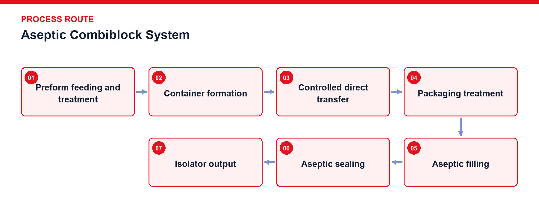
Preform Feeding and Treatment: Preform sanitization or treatment under controlled conditions.
Container Formation: Bottle formation within the project-defined controlled system boundary.
Controlled Direct Transfer: Neck-clamped transfer starwheels moving sterile containers through sealed isolator tunnels.
Packaging Treatment: Project-defined treatment of the preform, bottle and cap route before filling.
Aseptic Filling: Filling of product within the defined controlled boundary.
Aseptic Sealing: Rotary capper sealing containers under protected sterile airflow.
Isolator Output: Sealed containers exiting the sterile barrier via validated transition zones.
The aseptic combiblock integrates container manufacturing, packaging treatment, aseptic filling, and sealing into an uninterrupted containment boundary. Product is thermally treated in upstream UHT systems, cooled, and conveyed via hermetic piping to the filler, while preforms and caps undergo validated treatment protocols. System hygiene is maintained by an interdependent matrix comprising aseptic product circuits, sterile water and air supplies, packaging treatment units, isolator enclosures, and automated CIP, SIP, COP, and SOP sequences. No single subsystem can compensate for a compromise in overall boundary integrity. Pre-production routines mandate rigorous cleaning, sterilization, media establishment, and environmental recovery. During production, product temperature, isolator pressure differentials, door status, sterile media flow, and valve position interlocks govern operating permission.
Scroll horizontally to see all table columns.
| Design Object | Technical Description |
|---|---|
| Product Route | Product thermal treatment, cooling and closed transfer to the filler are defined from the beverage and process route. |
| Packaging Treatment | The treatment route for preforms, bottles and caps is selected from packaging materials and project requirements. |
| Direct Transfer | Shortened transfer path from blow molding to filling maintains container sterility while preserving neck reference and synchronized speed. |
| Isolator and Airflow | Barrier isolators, filtered sterile air supply, and positive differential pressure management protect critical zones from external contamination. |
| Aseptic Product Circuit | Valve groups, product piping, filling valves, and return loops support production, CIP, and SIP operating modes. |
| Open Surface Treatment | COP/SOP spray systems sanitize isolator interiors and exposed equipment surfaces while isolating sensitive blow molding mechanisms. |
| Fault Recovery | Interruption duration, door openings, media drops, or temperature deviations determine whether local recovery or full re-sterilization is executed. |
| Process Records | Project-defined records of relevant product, air, valve and operating conditions support the agreed validation and traceability approach. |
Scroll horizontally to see all table columns.
| Component | Function |
|---|---|
| Blow Molding and Transfer Unit | Forms containers and minimizes open transport distance under hygienic conditions. |
| Packaging Treatment Unit | Applies the project-defined treatment route to preforms, bottles and caps. |
| Aseptic Product Circuit | Connects UHT, aseptic surge tanks, valve blocks, and filling valves. |
| Isolator Cabinets and Air Handling | Encloses critical filling zones and maintains sterile conditioned air pressure. |
| CIP/SIP/COP/SOP Subsystems | Executes cleaning and sterilization for closed product loops and open isolator surfaces. |
Prior to production, product circuits, filling valves, and critical media undergo automated cleaning, sterilization, and status validation, while packaging materials are surface-treated before entering the sterile core. Product enters the filler via hermetic piping, meeting sterilized containers and caps within the isolator enclosure for immediate sealing. Aseptic runtime depends on boundary continuity. Isolator pressure, sterile media parameters, product temperature, valve positions, and enclosure door status form an active safety interlock loop; any breach triggers controlled shutdown and recovery procedures.
Closed product circuits and open isolator surfaces utilize distinct cleaning procedures and validation criteria. Isolator door seals, filtered air supplies, and drainage sumps must maintain structural and functional integrity. Packaging treatment media preparation, delivery, and recovery systems require dedicated maintenance. Maintenance access, component replacement, and recovery protocols must be documented and repeatable.
Preform, bottle, or combination packaging treatment configurations.
Project-specific filling, buffering, valve and data-recording configurations to be confirmed from the beverage and hygiene route.
Container formation, packaging treatment, product filling and capping are organized within a continuous controlled boundary. Product, air, packaging treatment, isolation, cleaning and operating conditions must be maintained together; no single subsystem replaces the integrity of the complete boundary.
The recovery scope is defined from the affected boundary. Product temperature, isolation status, aseptic media, valve mode and door status are assessed through the project procedure before controlled production recovery.
Provide the product formulation, thermal treatment route, container and cap materials, packaging-treatment requirement, planned operating period, aseptic utilities and validation boundary.
Provide your product, packaging, hygiene-route, utilities and validation requirements to begin aseptic project definition.
Discuss your project