Application scope
- Single-use large-format PET drinking-water containers
- Other large-format PET containers subject to preform and mold evaluation

PET Blow Molding and Bottle Handling
Large-capacity PET blow molding machines are engineered for the on-site forming of single-use large PET containers.
Project fit snapshot
Suitability depends on the product, container, output, hygienic route and connected equipment. Conditions outside the published scope require engineering review.
Technical content: fourth editionProject records shown below are project-specific references, not standard specifications.
Large-capacity PET blow molding machines are engineered for the on-site forming of single-use large PET containers. The equipment builds upon standard stretch blow molding principles by incorporating extended heating lengths, enlarged mold cavity spaces, enhanced blowing capacities, prolonged cooling times, and specialized container support structures to manage large preforms.
Large-format containers require project-specific consideration of preform thermal load, stretch travel, mold cooling time and container-transfer support. The final heating and blowing settings are established from the confirmed preform and bottle design.
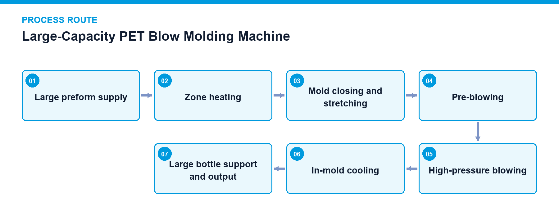
The large-capacity blow molding machine processes large PET preforms through heating, stretching, pre-blowing, high-pressure blowing, in-mold cooling, and container output stages. While maintaining fundamental stretch blow molding principles, the heating chamber length, mold frame dimensions, air volume, and cooling dwell times are re-engineered to accommodate large container geometries.
As container volume increases, preform thermal distribution and mold heat dissipation significantly impact production rhythms. Neck finish protection, base forming, handle areas, and sidewall thickness distribution are adjusted through coordinated preform selection, mold design, and blowing recipes.
Because large empty containers possess limited structural rigidity, output handling incorporates neck clamping or bottom support mechanisms to prevent swaying, deformation, or mechanical stress during transfer.
Preform and Container Specifications: Uses preform weight, neck finish, volume, maximum diameter, and height as primary design inputs.
Heating Length: Configures multi-zone heating tailored to large preform lengths while restricting neck and support ring temperatures.
Stretching and Pre-Blowing: Coordinates stretch rod travel, pre-blowing timing, and pressure to establish target material wall distribution.
High-Pressure Air Supply: Calculates air storage, filtration, pipe dimensions, and valve manifolds based on simultaneous cavity blowing volume and consumption rates.
Mold Cooling: Regulates cooling water temperature, flow rate, and circuit distribution to govern in-mold dwell times and production stability.
Container Support and Output: Implements neck clamping or base support during bottle discharge and downstream handover to protect container posture.
Scroll horizontally to see all table columns.
| Component | Function |
|---|---|
| Extended Heating Furnace | Provides sufficient heating length and zoned power regulation for large preforms |
| Heavy-Duty Mold Frame | Accommodates oversized molds and maintains secure clamping forces during high-pressure blowing |
| Stretching and Pneumatic System | Adjusts stroke length and timing ratios to match large preform dimensions and container volumes |
| Mold Cooling Unit | Removes forming heat from large containers and stabilizes continuous production states |
| Support and Output Mechanism | Mitigates sway and deformation of large empty containers during transfer |
Preform Feed and Loading: Verifies preform specifications, orientation, and rail feed levels.
Zoned Heating: Invokes bottle-specific thermal recipes while monitoring heating zone status.
Mold Closing and Stretching: Permits axial stretching and blowing only after mold position confirmation.
Pre-Blowing and High-Pressure Blowing: Establishes longitudinal and radial container expansion according to strict timing sequences.
In-Mold Cooling and Exhaust: Authorizes mold opening strictly after completion of cooling and pressure relief cycles.
Support and Output: Confirms container release, stable posture, and downstream receiving readiness.
Preform temperature recipe management
Mold closing position and high-pressure blowing interlocks
High-pressure air low-pressure protection
Cooling water flow rate and temperature monitoring
Large container discharge position detection
Ensure stability of high and low-pressure air filtration, drainage, and supply pressure.
Prevent contamination of heating lamps, reflectors, and preform clamping elements to maintain uniform thermal transfer.
Maintain mold cooling water channels, exhaust grooves, and parting faces in accordance with changeover schedules.
Re-verify mechanical positioning and blowing recipes following mold or stretch rod replacements.
Multi-format molds and quick-change tooling for diverse container sizes
Neck clamping or bottom support output handling assemblies
Container inspection and defective bottle rejection units
High-pressure air recovery systems and utility monitoring
Project reference only — not a standard specification.
Scroll horizontally to see all table columns.
| Application / Project Item | Configuration / Specifications | Usage Boundary |
|---|---|---|
| Large-Container Blow Molding | Capacity and configuration are project-specific | Final output is confirmed from bottle design, preform specification and equipment configuration |
Due to the limited rigidity of large-format empty containers, specialized neck clamping or bottom support mechanisms are integrated into the output stage to prevent swaying and mechanical distortion during transfer.
Cycle speeds are constrained by the thermal capacity of large preforms, mold heat dissipation rates, and exhaust/cooling dwell times, requiring evaluation against specific container designs.
Provide your large-format container dimensions, target output, and facility requirements to receive a customized technical evaluation and system configuration.
Discuss your project