Application scope
- PET bottled drinking water production lines.
- Small-format bottled water manufacturing facilities.
- Production lines requiring minimized open container transport distances.
Integrated Combiblock Systems
The bottled water combiblock system integrates preform heating and stretch blow molding, direct container transfer, drinking water filling, and rotary capping into a continuous wet-end sequence.
Project fit snapshot
Suitability depends on the product, container, output, hygienic route and connected equipment. Conditions outside the published scope require engineering review.
Technical content: fourth editionProject records shown below are project-specific references, not standard specifications.
The bottled water combiblock system integrates preform heating and stretch blow molding, direct container transfer, drinking water filling, and rotary capping into a continuous wet-end sequence. Once formed, PET bottles transfer directly into the filling area rather than through a long-distance empty-bottle route, allowing blow molding, filling, and capping to be coordinated by one production rhythm. Water treatment, compressed air and cleaning circuits retain their own defined operating boundaries.
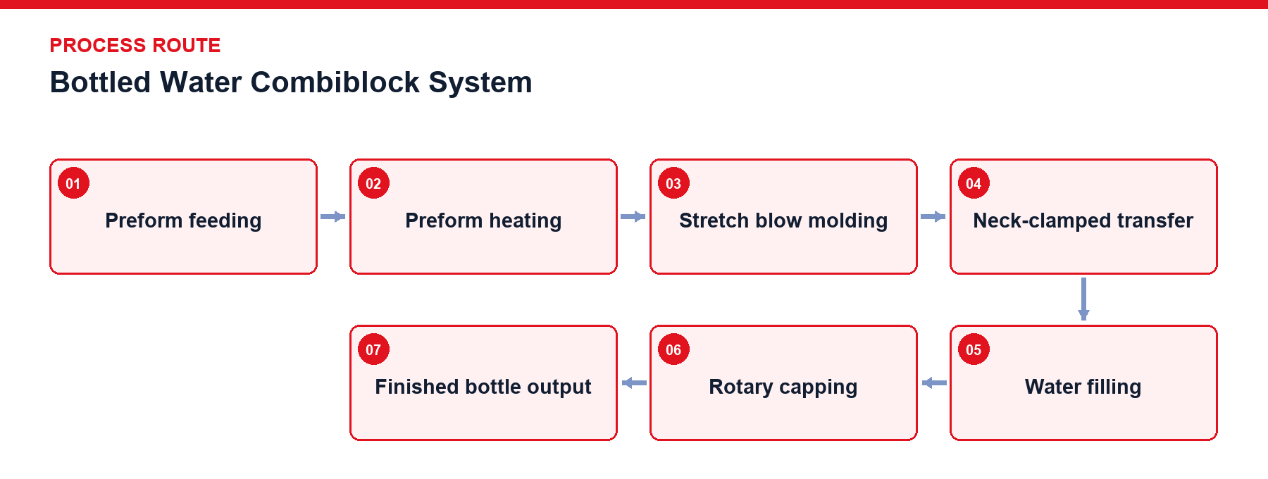
Preform Feeding: PET preform supply to the blowing section.
Preform Heating: Controlled thermal preparation of preforms before bottle forming.
Stretch Blow Molding: Axial stretching and high-pressure blowing inside mold cavities.
Neck-Clamped Transfer: Direct container transfer via neck support starwheels.
Water Filling: Filling to the project-defined liquid level.
Rotary Capping: Capping with the specified bottle closure.
Finished Bottle Output: Discharge to downstream conveying and inspection systems.
The primary design focus of the bottled water combiblock is converging preform supply, compressed air, product water, cap supply, and finished containers under a single machine cycle. Heating and blowing capacities, filling valve counts, capping rates, and downstream transport must be calculated using identical bottle types and target speeds. Formed bottles enter the filling zone through starwheels or direct transfer mechanisms, reducing the swing, tipping, and surface exposure associated with lightweight empty containers in conventional air conveyors. Direct mechanical connection does not remove functional process boundaries: high-pressure blowing air, mold cooling, product water feed, Clean-In-Place (CIP), and cap supply maintain their respective operational interlocks. For 24,000 BPH water lines, project definitions encompass preform, label, packaging, pallet, building, and utility inputs to jointly establish engineering boundaries prior to equipment configuration.
Scroll horizontally to see all table columns.
| Design Object | Technical Description |
|---|---|
| Unified Speed Baseline | Blow molding, filling, capping, and downstream transport operate on a single target bottle speed reference with defined deceleration and recovery sequences. |
| Direct Transfer | Neck-based container transfer secures stable conveyance from blow molding release to the filling table, controlling starwheel positioning and container engagement. |
| Water Supply Stability | Product water storage tanks, supply pumps, and filler bowls maintain continuous liquid feed to prevent upstream hydraulic fluctuations from entering the filling zone. |
| Cap Supply | Cap supply is coordinated with the capping section and participates in defined operating permits. |
| Cleaning Boundary | Filling supply and cleaning interfaces are defined together with the applicable CIP route. |
| System Interlocks | Material availability, equipment status and downstream blockage conditions participate in coordinated operating control. |
Scroll horizontally to see all table columns.
| Component | Function |
|---|---|
| Blow Molding Unit | Executes preform heating, axial stretching, pre-blowing, high-pressure blowing, and mold cooling. |
| Direct Transfer Unit | Transfers formed empty containers directly into the filling zone based on neck support. |
| Filling Unit | Fills drinking water through the defined filling system. |
| Capping Unit | Applies the specified bottle cap after filling. |
| Cleaning Interface | Defines the applicable cleaning connection and process boundary for the filling system. |
Preforms are heated to establish the temperature distribution required for stretch blow molding, then enter molds for axial stretching, pre-blowing and high-pressure blowing. Formed bottles are transferred directly to the filling section through the defined transfer mechanism. The water-supply circuit maintains the filler liquid level; bottles are filled at the filling position and capped immediately. The three main process stages are linked through a common speed reference and material-status signals. Controls coordinate material availability, blow-molding conditions, filling supply, capping and downstream blockage conditions.
Blow-molding and wet filling sections require separately defined cleaning and maintenance boundaries. Neck-handling components, transfer parts and capping components must be assessed for the confirmed bottle and cap format. Before production, the filling and cleaning interfaces must be checked for correct connection and drainage according to the project procedure.
High-pressure air recovery and staged air supply systems.
Preform temperature inspection and defective bottle rejection units.
Cap handling sanitization or neck rinsing modules.
Machine status, alarm logging, recipe management, and batch event recording.
Project Reference Only — Not a Standard Specification
The figures below apply exclusively to the specified project configuration to illustrate engineering matching against specific products and capacities; they do not represent standard performance metrics for other projects.
Scroll horizontally to see all table columns.
| Project Item | Project Scope | Configuration / Value | Boundary Conditions |
|---|---|---|---|
| 24,000 BPH 330 mL PET Water Combiblock Line | Whole-Line Input | Preforms, caps, labels, packaging, pallets, building, and utility conditions | Standard engineering relationships apply |
| 24,000 BPH 330 mL PET Water Combiblock Line | Downstream Path | Blow drying, coding, conveying, labeling, film wrapping/cartoning, palletizing, and tray flow | Third-party specialized machines excluded |
The system transfers formed bottles directly from the blowing section to the filling section through the defined transfer mechanism, reducing the need for long-distance empty-bottle transfer between separate machines.
Product water storage tanks, supply pumps, and filler bowls maintain continuous liquid feed to stabilize fluid delivery and prevent upstream hydraulic fluctuations from entering the filling valves.
Operation is governed by interlocks covering track preform fullness, blow molding temperatures, high-pressure air availability, no-bottle-no-fill/cap logic, filler bowl levels, and downstream line blockages.
Send your bottle, preform, cap, target BPH, packaging route and plant-utility information to begin a combiblock project definition.
Discuss your project