Application scope
- Drinking water PET bottles
- Juice and tea beverage heat-resistant PET bottles
- Carbonated soft drink (CSD) PET bottles

PET Blow Molding and Bottle Handling
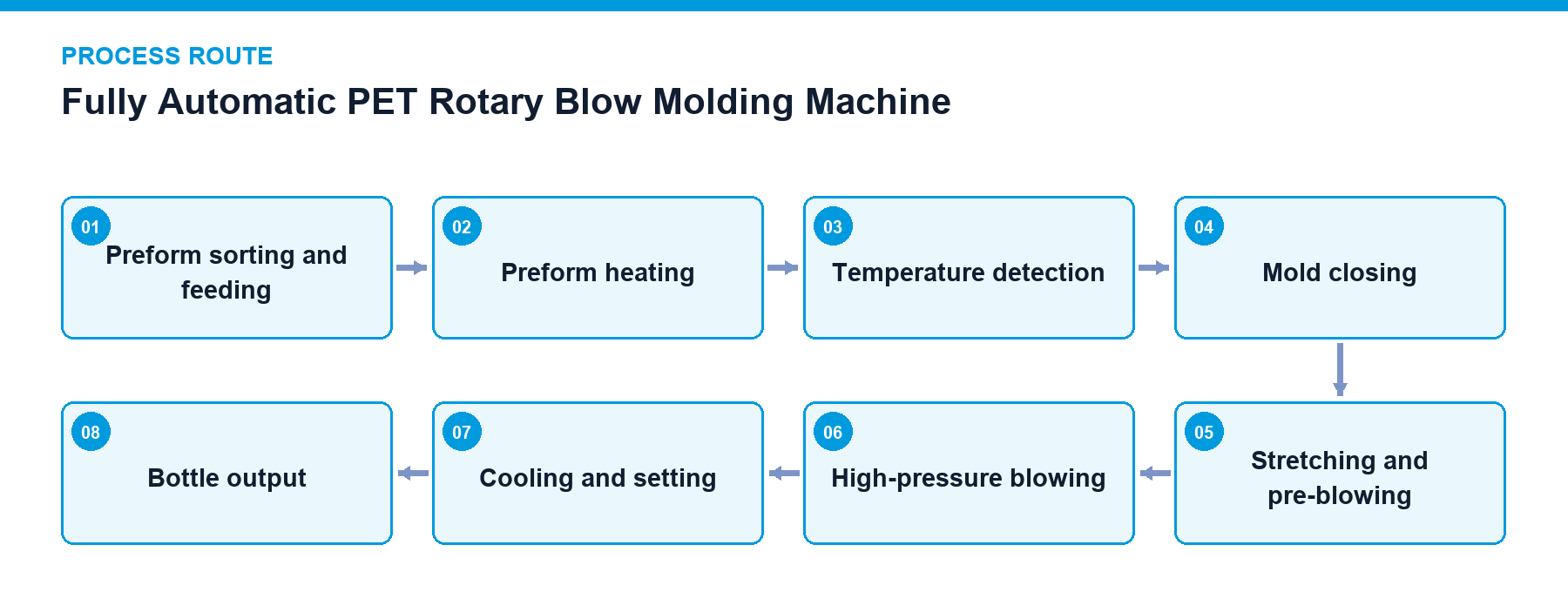
A fully automatic PET rotary blow molding machine heats preforms to suitable stretching temperatures, executes axial stretching, pre-blowing, and high-pressure blowing inside mold cavities, and continuously outputs formed bottle bodies after cooling and setting.
Project fit snapshot
Suitability depends on the product, container, output, hygienic route and connected equipment. Conditions outside the published scope require engineering review.
Technical content: fourth editionProject records shown below are project-specific references, not standard specifications.
A fully automatic PET rotary blow molding machine heats preforms to suitable stretching temperatures, executes axial stretching, pre-blowing, and high-pressure blowing inside mold cavities, and continuously outputs formed bottle bodies after cooling and setting.
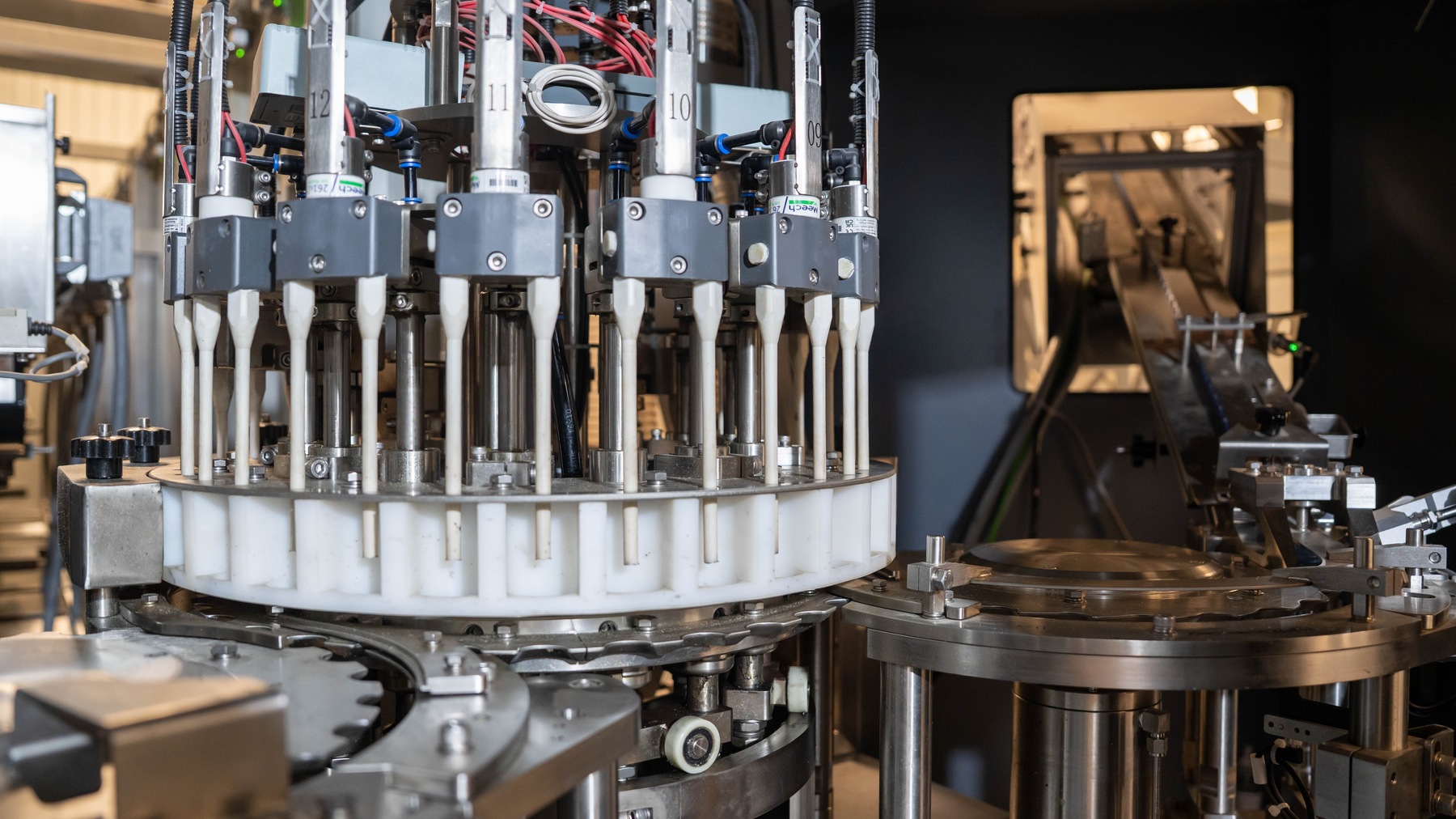
Equipment detail — rotary stretch blow molding station.
Container consistency, wall thickness distribution, and neck integrity govern downstream filling reliability, capping performance, and package pressure resistance. Maintaining precise thermal and pneumatic synchronization prevents bottle distortion, minimizes material waste, and ensures dependable packaging integrity across varied beverage production speeds.
The operational stability of the blow molding process relies on the coordination of thermal, pneumatic, and stretching mechanisms. Preforms rotate continuously within the infrared heating zone to ensure uniform circumferential heating, while the neck finish is thermally restricted by cooling structures to prevent deformation, and the preform body establishes an axial heating profile.
Heated preforms enter the mold assemblies. Once mold closing is confirmed, sequential axial stretching and pre-blowing are performed, followed by high-pressure blowing and cooling setting. Servo-driven mechanisms control mold closing, pitch transfer, transport, and stretching. Preform temperature, air pressure, cooling water, safety doors, and jammed preform status collectively govern blowing authorization.
The blow molding machine operates in coordination with high-pressure air systems, storage tanks, filters, dryers, and mold cooling systems. While high-pressure air equipment is external to the main machine body, its pressure, flow rate, dew point, and storage capacity directly govern continuous production performance.
Preform Sorting and Conveying: Bulk preforms are elevated, oriented, and fed into the heating chain via guide rails, with rail stock levels regulating upstream operation.
Zone Heating: Multi-zone lamp outputs, preform rotation, and active cooling establish preform body temperature profiles.
Neck Protection: Prevents excessive heating of the neck finish and support ring to preserve subsequent gripping and sealing datums.
Stretching and Pre-Blowing: Stretch rod position, speed, and pre-blow timing determine material distribution in axial and circumferential directions.
High-Pressure Blowing: High-pressure air forces material to conform to mold cavities, with air volume and pressure calculated based on bottle geometry and cavity count.
Mold Cooling: Chilled water removes forming heat and influences demolding temperature and container stability.
Air Recovery: Systems can recover a portion of high-pressure exhaust air for low-pressure actuation or other compatible pneumatic circuits.
Recipe and Changeover: Synchronizes heating, stretching, blowing, and transport parameters when switching preform specifications, bottle designs, or production speeds.
Scroll horizontally to see all table columns.
| Component | Function |
|---|---|
| Preform Feeding Unit | Organizes bulk preforms and feeds them into the heating zone at a regulated pace |
| Infrared Heating System | Establishes axial and circumferential temperature profiles via preform rotation and zoned lamp outputs |
| Mold Closing and Stretching Mechanism | Locks mold assemblies and drives stretch rods to achieve axial orientation |
| Pre-Blowing and High-Pressure Blowing Unit | Executes preliminary container expansion and mold conformation according to strict timing sequences |
| Cooling and Bottle Output Unit | Cools bottle necks and molds, transferring finished containers reliably to downstream transport |
Preform Elevation and Sorting: Track high and low levels coordinate elevator and sorter operation.
Infrared Heating: Regulates lamp zone outputs, air cooling, and preform rotation according to stored recipes.
Temperature and Position Confirmation: Prevents blowing authorization if abnormal preforms or equipment states are detected.
Mold Closing and Stretching: Confirms mold locking and stretch mechanism positions before actuation.
Pre-Blowing and High-Pressure Blowing: Opens pneumatic circuits according to timing sequences while monitoring high-pressure air status.
Cooling, Exhaust, and Output: Releases pressure and demolds containers after setting, transferring them to downstream equipment.
Track level monitoring and feed start/stop control
Preform temperature and heating output regulation
Mold closing position verification and blow authorization
High-pressure air and cooling water status monitoring
Abnormal preform and jam detection
Safety door and main drive interlocks
Lamps, reflectors, heating chains, and preform rails must remain free of dust to prevent heating and transport interference.
Stretch rods, sealing elements, blowing valves, and mold cooling channels are priorities for periodic maintenance.
Mechanical positioning, neck datums, stretch strokes, and blowing recipes must be verified following mold changeovers.
Compressed air filtration and drying conditions must be incorporated into startup prerequisites and daily logs.
Preform temperature detection and defective preform rejection
High-pressure air recovery systems
Servo-driven stretch, pitch transfer, and mold closing mechanisms
High and low-pressure air compressor units, storage tanks, filters, and dryers
Project reference only — not a standard specification.
Scroll horizontally to see all table columns.
| Application / Project Item | Configuration / Specifications | Usage Boundary |
|---|---|---|
| 10,000 BPH, 300 mL PET Water Line | Six-cavity automatic blow molder, 10,000 BPH design capacity | Project configuration |
| 10,000 BPH, 330 mL PET CSD Line | Six-cavity full-servo blow molder, 10,000 BPH design capacity | Project configuration |
| 48,000 BPH, 330 mL PET CSD Line | 24-cavity rotary blow molding unit | Project configuration |
| 10,000 BPH, 300 mL PET Water Line (Equipment Record) | 6 cavities; sample capacity for 0.5 L bottle is 12,000–13,000 BPH | Equipment specification record |
| 10,000 BPH, 300 mL PET Water Line (Utilities) | 118 kW installed power; Low-pressure air 1 MPa / 1.0 m³/min; High-pressure air 3 MPa / 10 m³/min | Equipment specification record |
| 10,000 BPH, 300 mL PET Water Line (Cooling) | 2–4 bar, approx. 6 m³/h, recorded inlet water temperature 18°C | Project record, verify against site conditions |
| 5,000 BPH, 500 mL PET Juice Hot-Fill Line | 4 cavities; 0.5 L sample capacity 6,000 BPH | Equipment specification record |
| 5,000 BPH, 500 mL PET Juice Hot-Fill Line (Utilities) | 77 kW installed power; High-pressure air 3.5 MPa / 6 m³/min, low-pressure air 1 MPa / 1 m³/min | Equipment specification record |
| 10,000 BPH, 330 mL PET CSD Line (Equipment Record) | 6 cavities; 0.5 L CSD bottle sample capacity 10,000 BPH | Equipment specification record |
Preforms rotate continuously past multi-zone infrared lamps, allowing independent power adjustments per zone while active cooling protects the neck finish and establishes specific axial and circumferential temperature distributions.
Blowing authorization requires confirmed preform temperature compliance, closed mold position, correct stretch rod positioning, valid safety door interlocks, and stable high-pressure air supply status.
Consult our engineering team with your container specifications, neck standards, and target production capacity to determine the optimal blow molding configuration for your plant.
Discuss your project