Scope of Application
Scroll horizontally to see all table columns.
| Application Route | Target Products & Containers |
|---|---|
| Aseptic Filling | Acidic and low-acid fruit juices, tea beverages, and liquid products requiring extended ambient shelf-life. |
| Ultra-Clean Filling | Beverages requiring enhanced microbiological control beyond standard gravity filling. |
| Hot Filling | PET and glass containers for fruit juices, teas, and functional non-carbonated drinks. |
| Bottled Water Filling | Non-carbonated still drinking water in PET bottles. |
| Gallon Water Filling | Returnable 12 to 19-liter large-format polycarbonate water containers. |
| CSD Filling | Carbonated soft drinks, sparkling water, and mineral water. |
| Specialized Solutions | Alcoholic beverages, condiments, and edible oils via dedicated application routes. |
Process Path
Scroll horizontally to see all table columns.
| Sequence | Process Stage |
|---|---|
| 01 | Upstream product supply (thermal treatment, mixing, or carbonation). |
| 02 | Container feeding, rinsing, or sterilization treatment. |
| 03 | Closure handling, sorting, and decontamination. |
| 04 | Quantitative liquid dosing in controlled filling zones. |
| 05 | Closure application and secure sealing. |
| 06 | Downstream processing (inversion, cooling, drying, inspection, and packaging). |
System Design and Operating Logic
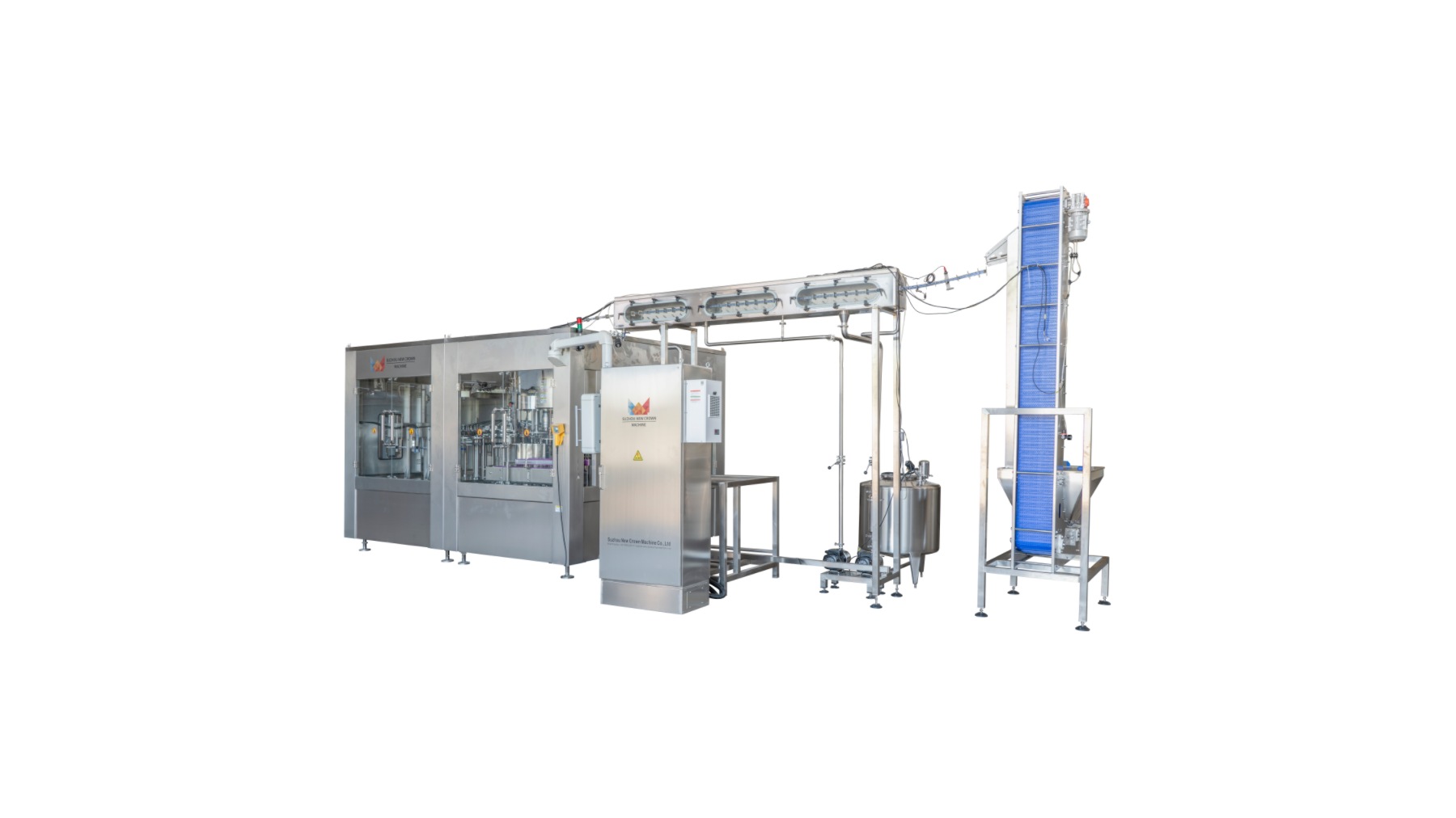
The filling family coordinates container handling, liquid dosing, and closure application within continuous mechanical or hygienic boundaries. Equipment configurations are structured according to specific product routes: water and non-carbonated still beverages utilize gravity or constant-level volumetric principles; hot filling operates as a continuous temperature process with subsequent inversion and multi-zone spray cooling; aseptic and ultra-clean systems establish controlled isolation barriers and enhanced packaging decontamination; CSD systems employ equal-pressure (isobaric) mechanics to balance container gas pressure with product bowl pressure.
Filling machines do not operate as isolated units; they require coordinated integration with upstream thermal treatment, mixing, carbonation, or buffer systems, as well as downstream conveying, cooling, and packaging equipment. Valve types, feed pressures, recirculation modes, and changeover protocols are established based on product characteristics and technical agreements.
Key Design Details
Scroll horizontally to see all table columns.
| Design Element | Technical Specification |
|---|---|
| Hygienic Boundaries | Product circuits, packaging treatment, isolation barriers, and environmental controls are structured according to product requirements. |
| Valve and Dosing Mechanics | Channel geometry, valve types, and volumetric control principles are matched to product viscosity, pulp content, or carbonation. |
| Container & Closure Handling | Rinsing, decontamination, feeding, and sealing mechanisms are aligned with container geometry and neck finish. |
| Cleaning and Sterilization | Closed fluid circuits incorporate Clean-in-Place (CIP) and Sterilization-in-Place (SIP) routines, while open surfaces utilize cleaning and sanitization protocols. |
| Interlocks & Safety | Safety interlocks manage container presence, closure supply, fluid levels, operating temperatures, and line synchronization. |
Major Components and Functions
Scroll horizontally to see all table columns.
| Component | Primary Function |
|---|---|
| Product Supply & Buffer | Delivers treated liquid at controlled temperature, pressure, and flow rates to filling equipment. |
| Container & Closure Units | Executes sorting, rinsing, decontamination, feeding, and positioning of packaging materials. |
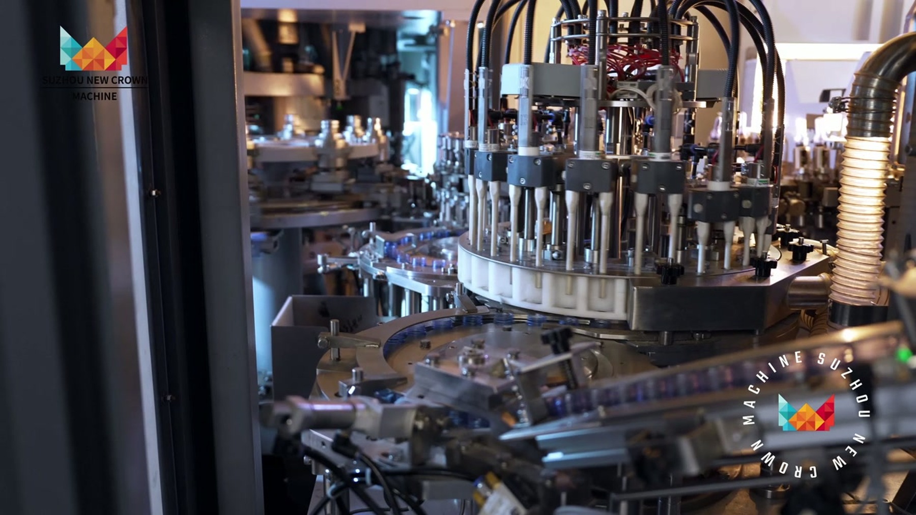
| Filling Turrets & Valves | Performs quantitative liquid dosing adapted to fluid properties and pressure/gravity requirements. |
| Capping Units | Applies screw caps, crowns, or press-on closures with controlled torque or force. |
| Cleaning & Utility Interfaces | Connects product circuits and equipment surfaces to CIP/SIP systems and utility supplies. |
Operation and Control
State Interlocks: Operating permissions depend on product temperature, fluid levels, cleaning validation, and safety barrier statuses.
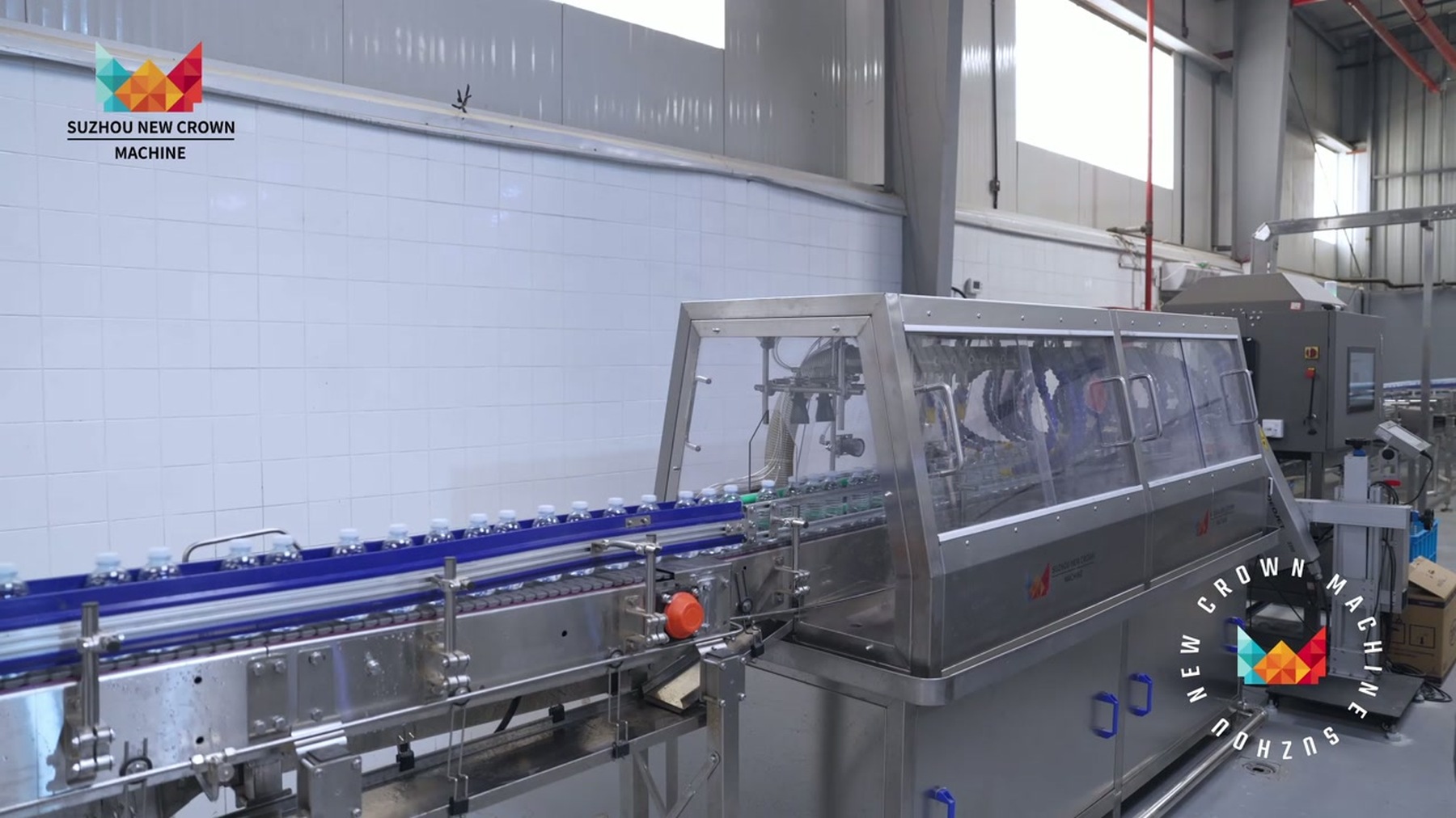
Line Synchronization: Infeed, filling, capping, and discharge starwheels coordinate container transfer to prevent jams and material waste.
Exception Management: Stoppages trigger automated logic for fluid recirculation, temperature management, or equipment pausing based on stoppage duration.
Process Monitoring: Key parameters including liquid levels, pressures, temperatures, and valve positions are managed through centralized control systems.
Cleaning, Maintenance, and Changeover
Cleaning Protocols: Closed fluid loops utilize CIP/SIP procedures, while equipment exteriors and isolation surfaces utilize designated cleaning and sanitization routines.
Maintenance Inspection: Seals, valves, nozzles, filters, and mechanical drive components are inspected and maintained according to operating schedules.
Changeover Management: Format parts, guide rails, and changeover tooling are cleaned and adjusted when switching container sizes or product types.
Engineering Interfaces
Scroll horizontally to see all table columns.
| Interface Category | Connected System Elements |
|---|---|
| Upstream Interface | UHT systems, plate heat exchangers, carbonation mixers, bulk water storage, or air conveyors. |
| Downstream Interface | Container inversion units, cooling tunnels, blow dryers, labeling machines, and packaging lines. |
| Utility Interfaces | CIP/SIP systems, sterile water, compressed air, cooling water, electrical power, and steam. |
Project Definition Inputs
- Product formulation, viscosity, pulp content, acidity, and carbonation level.
- Target shelf-life and required microbiological hygiene level (Aseptic, Ultra-Clean, Hot Fill, Standard).
- Container material (PET, glass, 2-piece can, 19 L returnable polycarbonate), neck finish, and volume.
- Target hourly production capacity (BPH / BPM).
- Plant utility availability and factory layout constraints.
Options and Integration Items
- Integration of aseptic, ultra-clean, hot fill, water, or CSD monoblock configurations.
- Selection of specialized valve types for pulpy, viscous, or carbonated products.
- Automated cap handling, sorting, inspection, and decontamination systems.
- Advanced process data recording and line supervision interfaces.
Project Reference
Project Reference Only — Not a Standard Specification
- Product Forms Integration: Pulp-containing beverages are integrated into hot filling or corresponding hygienic filling systems using dedicated flow channels and valve types rather than separate parallel lines. Glass bottle clean filling and 2-piece can filling/seaming are integrated into the filling system family with project-specific container handling, rinsing, filling, and sealing interfaces.
- Engineering Boundaries: All processing speeds, utility consumptions, and footprint dimensions are established based on individual project technical agreements and verified product trials.
Frequently Asked Questions
How are different beverage categories accommodated within the filling system family?
Filling systems are configured according to product characteristics, utilizing distinct routes such as aseptic cold fill, hot fill, isobaric CSD filling, gravity water filling, or multi-stage gallon washing.
Are filling system line speeds universal across different container sizes?
No. Hourly production capacity depends on container volume, neck finish, fluid foaming characteristics, and change-over tooling. Capacities must be verified for each specific project.
How is cleaning managed across different filling system configurations?
Closed fluid loops utilize Clean-in-Place (CIP) and Sterilization-in-Place (SIP) routines with dedicated dummy cups, while equipment surfaces utilize designated cleaning and sanitization protocols.
Call to Action
Consult our engineering team to evaluate your product specifications and configure an industrial beverage filling system tailored to your production objectives.
Discuss your project