Application scope
- Carbonated soft drinks.
- Carbonated sparkling water.
- Carbonated mineral water.
Integrated Combiblock Systems
The CSD combiblock system integrates PET blow molding, isobaric filling, and capping into a continuous wet end.
Project fit snapshot
Suitability depends on the product, container, output, hygienic route and connected equipment. Conditions outside the published scope require engineering review.
Technical content: fourth editionProject records shown below are project-specific references, not standard specifications.
The CSD combiblock system integrates PET blow molding, isobaric filling, and capping into a continuous wet end. Upstream blending and carbonation systems supply low-temperature, pressurized, and gas-stable product, while the filling machine completes operations through pressure balancing, liquid admission, gas return, and controlled pressure release.
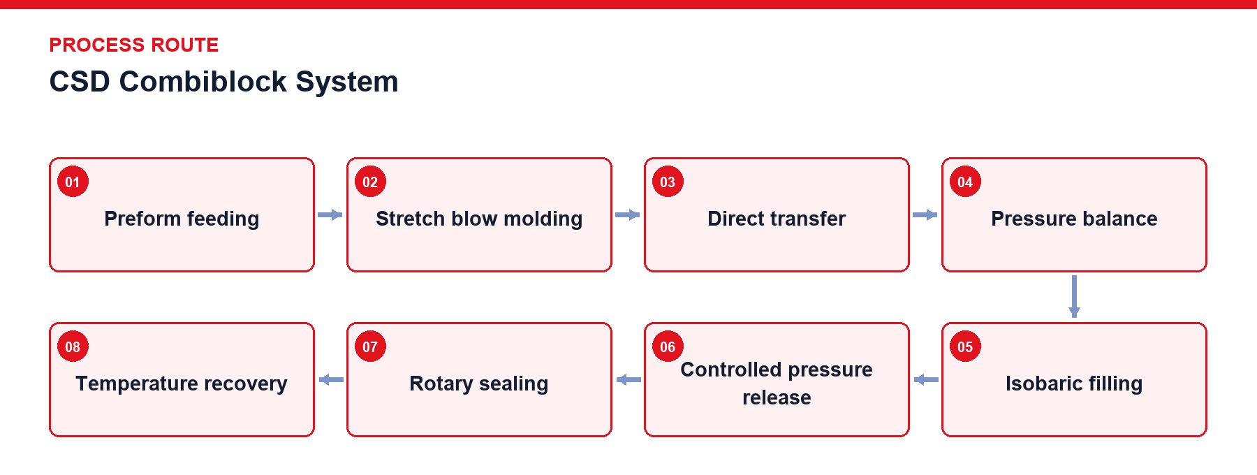
Preform Feeding: Automated preform orientation and infeed.
Stretch Blow Molding: Container formation in blow molding cavities.
Direct Transfer: Neck-clamped transfer into the filling zone.
Pressure Balance: Equalizing pressure between container and filler bowl.
Isobaric Filling: Gas-balanced liquid admission and gas return.
Controlled Pressure Release: Gradual pressure reduction before valve release.
Rotary Sealing: Capping under stable product state.
Temperature Recovery: Downstream warming or temperature conditioning.
Beyond container formation and sealing, the CSD combiblock must maintain the low temperature, pressure, and gas-liquid balance of carbonated products. Upstream mixers, pressurized product tanks, and filler bowls must coordinate continuously; any temperature rise, feed pressure drop, or liquid level fluctuation can result in increased foaming, unstable liquid levels, or capacity reduction. Isobaric filling valve cycles include container sealing, pressure balancing, liquid admission and gas return, inlet closure, and controlled pressure release. Excessive release speed disturbs product, while insufficient release affects container exit and subsequent capping; consequently, valve timing must be tuned with product temperature, carbonation state, and bottle geometry.
Scroll horizontally to see all table columns.
| Design Object | Technical Description |
|---|---|
| Pressurized Feed | Mixer product tanks, feed piping, and filler bowls maintain coordinated pressure to prevent product state changes. |
| Low-Temperature Boundary | Refrigeration capacity, piping heat gain, and short-stop duration determine actual filling inlet temperatures. |
| Pressure Balance | Pressure equalization is established between the container and product cylinder prior to opening the liquid valve. |
| Gas Return and Level | Displaced container gas exhausts through return paths, with valve structures and timing establishing fill stop levels. |
| Controlled Pressure Release | Multi-stage pressure relief is executed before leaving the filling valve to limit foaming and liquid splashing. |
| Timely Sealing | Capping is completed within a stable rhythm immediately following filling, followed by warming and downstream transport. |
| Whole-Machine Synchronization | Blow molding, filling, capping, warming, and packaging match identical production capacity requirements. |
Scroll horizontally to see all table columns.
| Component | Function |
|---|---|
| Blow Molding Unit | Forms PET containers per bottle geometry and supplies empty bottles directly to the filling zone. |
| Isobaric Filling Unit | Establishes pressure balance between container and product bowl before executing liquid fill and gas return. |
| Pressure Release Unit | Gradually releases excess container pressure prior to valve exit. |
| Capping Unit | Seals containers while carbonation state remains stable. |
| Pressurized Feed Interface | Coordinates temperature and pressure with carbonation, cooling, and buffering systems. |
Formed empty bottles enter filling valves and are sealed and positioned. Valves establish pressure balance before opening liquid channels, allowing product to flow down container walls while displaced gas exhausts through return paths. Upon reaching specified liquid levels, inlet flow stops and pressure releases according to programmed timing. Low temperature, carbonation state, and feed pressure influence foam and level stability. Automated controls monitor carbonated product temperature and pressure permits, filler bowl levels and pressure, no-bottle-no-fill and no-bottle-no-cap logic, cap shortage detection, and whole-machine speed reduction during downstream blockages.
Carbonated product bowls, filling valves, gas return paths, and feed piping integrate into automated CIP cleaning loops. Short-stop recovery requires confirming that temperature, pressure, and liquid levels have returned to permitted operational ranges. Capper torque mechanisms, sealing components, and isobaric valve moving parts require periodic inspection per maintenance schedules.
Preform temperature inspection, defective bottle recognition, and high-pressure air recovery.
Online product temperature, pressure, and feed status data logging.
Speed synchronization with bottle warmers, blow dryers, and labeling systems.
Project Reference Only — Not a Standard Specification
The figures below apply exclusively to the specified project configuration to illustrate engineering matching against specific products and capacities; they do not represent standard performance metrics for other projects.
Scroll horizontally to see all table columns.
| Project Item | Configuration / Operating Condition | Description |
|---|---|---|
| CSD Combiblock Line | 24-cavity blow / 110-valve fill / 30-head capper; design capacity 48,000 BPH (330 mL PET bottle) | Specific configuration corresponding solely to the referenced project. |
Isobaric filling valves establish pressure equilibrium between the product bowl and the PET container before liquid admission, while controlled multi-stage pressure release prior to valve exit limits foaming and splashing.
Low product temperature maintains carbon dioxide solubility and gas-liquid stability; temperature fluctuations alter carbonation pressure and cause foaming or level inconsistencies.
The system integrates with upstream carbonation and blending units, and downstream warming tunnels, blow dryers, labeling, and packaging machinery operating on synchronized speed baselines.
Maintain optimal carbonation, stable liquid levels, and high packaging output with our CSD combiblock systems. Contact our engineering specialists to configure your carbonated beverage production line.
Discuss your project