Application scope
- Beverage blending tanks and storage vessels
- Hygienic piping networks and valve assemblies
- Plate heat exchangers and material pumps

Pretreatment and Process Systems
The Clean-In-Place (CIP) Cleaning System circulates water, caustic solutions, acid solutions, and other cleaning media through tanks, piping, pumps, valves, heat exchangers, and filling circuits along established pathways without requiring the dismantling of primary process equipment, restoring internal product-contact surfaces to a clean state.
Project fit snapshot
Suitability depends on the product, container, output, hygienic route and connected equipment. Conditions outside the published scope require engineering review.
Technical content: fourth editionProject records shown below are project-specific references, not standard specifications.
The Clean-In-Place (CIP) Cleaning System circulates water, caustic solutions, acid solutions, and other cleaning media through tanks, piping, pumps, valves, heat exchangers, and filling circuits along established pathways without requiring the dismantling of primary process equipment, restoring internal product-contact surfaces to a clean state.
A CIP station must address three fundamental operational queries: the source of cleaning media, the specific product-contact surfaces traversed, and the conditions governing media return or discharge. Three-tank and dual-loop project configurations demonstrate that media storage, heating, chemical dosing, supply/return valve manifolds, concentration monitoring, and circulation pumps must be engineered as an integrated system.
Different cleaning objects may share central media tanks while operating along distinct supply and return pathways at any given moment. Dual-loop configurations permit two separate cleaning object groups to execute independent or coordinated programs according to established sequences, provided that pumps, heat exchangers, valve manifolds, and return capacities accommodate concurrent operating conditions.
Chemical concentration, temperature, duration, and flow dynamics collectively determine the completion of a cleaning stage. Chemical media and program parameters from prior projects serve strictly as configuration records; final cleaning protocols must be established in accordance with product residues, material compatibility, and validation standards.
Media Tank Group: Water, acid, caustic, or recovery media are stored in separate tanks configurable with thermal insulation, agitation, liquid level sensing, and cleaning connections.
Dosing and Concentration: Dosing pumps and concentration sensors establish, monitor, and adjust cleaning media conditions.
Supply and Return: Sanitary pumps, supply valves, and return valves select target circuits, maintaining circulation once media return is verified.
Media Heating: Plate heat exchangers, steam control valves, and temperature detectors form heating and constant-temperature control loops.
Dual-Loop Organization: Cleaning circuits are organized by equipment partitioning, cleaning duration, and return capacity to prevent cross-contamination or pump capacity contention.
Filtration and Drainage: Pipeline filters protect spray devices and valves, with discharge or recovery logic governed by media status and project engineering schemes.
Mode Interlocking: Production and cleaning valve positions are mutually exclusive; failure to connect target equipment or the opening of maintenance doors restricts program initiation.
Scroll horizontally to see all table columns.
| Component | Function |
|---|---|
| Water, Caustic, and Acid Tanks | Store and recover cleaning media across different operational stages |
| Circulation Pump | Supplies required cleaning flow rates to target circuits |
| Heating and Temperature Control | Maintains cleaning media temperatures during designated operational phases |
| Supply and Return Valve Group | Selects cleaning media, target equipment, and return flow pathways |
| Spray Balls, Spray Heads, and Filling Dummy Cups | Connect internal tank surfaces and filling valve outlets into circulation loops |
Scroll horizontally to see all table columns.
| Step | Operation | Control and Verification |
|---|---|---|
| 1 | Confirm Cleaning Objects and Circuits | Inspect target equipment, supply/return valve positioning, and drainage pathways. |
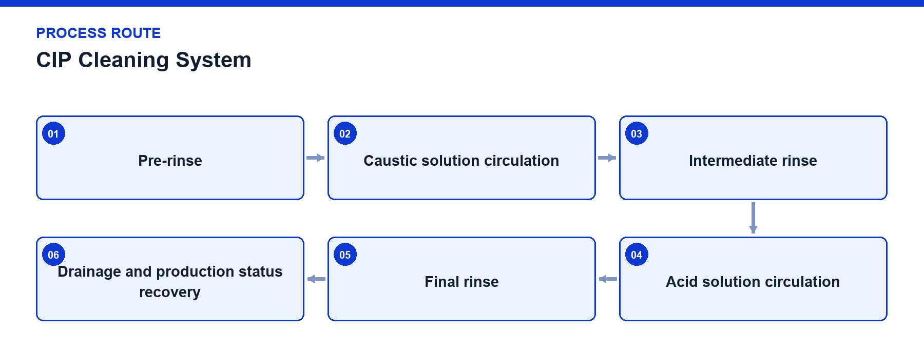
| 2 | Pre-rinse | Establish media return and monitor temperature, duration, or return status indicators. |
| 3 | Caustic Circulation | Control heating parameters, chemical concentration, liquid levels, and circulation pump operation. |
| 4 | Intermediate Rinse | Switch circuits based on return status verification to prevent direct mixing of acid and caustic media. |
| 5 | Acid or Supplementary Stage | Execute per project-specific programs; not configured as a fixed step for all product applications. |
| 6 | Final Rinse and Drainage | Confirm return status, valve position resetting, and production permit issuance. |
Cleaning media is delivered by the CIP station through supply lines into target equipment, traversing product-contact surfaces before returning via return headers. Tanks utilize spray heads to achieve surface coverage, while piping, pumps, and heat exchangers rely on continuous fluid circulation to remove residues. Filling machines employ automatic dummy cups or dummy bottles to close filling valve outlets into return piping loops. Production and cleaning valves maintain mutually exclusive control logic; system operation is restricted if cleaning objects are disconnected, tank levels are insufficient, media return is unestablished, or temperature limits are exceeded.
Recipe-driven cleaning stages and time management routines.
Interlocks governing temperature, liquid level, and return flow status.
Mutual exclusivity interlocks between production mode and cleaning mode valve positions.
Return conductivity monitoring to assist in stage transition timing when required.
Low points across media tanks, pumps, heat exchangers, and valve groups require complete drainage capabilities to prevent prolonged liquid stagnation and cross-contamination.
Concentration meters, conductivity sensors, and temperature probes require scheduled maintenance and calibration rather than relying solely on program timers.
Filling dummy cups, tank spray heads, and return branch connections must be verified for structural integrity following changeovers or maintenance.
Compatibility between chemical media, elastomeric seals, and metallic materials must be explicitly defined in technical agreements.
Project reference only — not a standard specification.
Scroll horizontally to see all table columns.
| Project Configuration | Parameter / Equipment Item | Configured Value / Description | Usage Boundary |
|---|---|---|---|
| 5,000 BPH, 500 mL PET Hot-Fill Juice Line | CIP Form | Acid, caustic, and water 3-tank CIP system with centrifugal pump circulation | Project configuration |
| 5,000 BPH, 500 mL PET Hot-Fill Juice Line | Cleaning Program Record | 2% NaOH, 2% HNO3, 80°C, 30 minutes parameters | For expert verification only |
| 48,000 BPH, 330 mL PET CSD Line | CIP Form | 3,000 L semi-automatic dual-loop CIP system featuring three insulated tanks | Project equipment schedule |
| 48,000 BPH, 330 mL PET CSD Line | Detection and Heating | Liquid level and concentration sensors, dosing pumps, 16 m² plate heat exchanger, steam regulation | Project equipment schedule |
| 5,000 BPH, 500 mL PET Hot-Fill Juice Line | Circulation Capacity | Recorded 1,500 L/h flow, 2.2 kW circulation pump, 24 m head | Project record; verify per circuit |
| 48,000 BPH, 330 mL PET CSD Line | Tanks and Circuits | 3,000 L tank group, semi-automatic dual-loop arrangement | Project equipment schedule |
| 48,000 BPH, 330 mL PET CSD Line | Heating Package | 16 m² plate heat exchanger with steam regulating valve and temperature control | Project equipment schedule |
While multiple equipment zones can share central storage tanks, concurrent dual-loop execution requires adequate pump capacity, heat exchanger duty, and return-flow management to prevent hydraulic interference or cross-contamination.
No. Cleaning parameters such as chemical concentration, temperature, and cycle duration are established based on specific soil characteristics, equipment metallurgy, and microbiological validation requirements for each project.
Contact our hygienic engineering experts to evaluate your plant layout and design an automated CIP cleaning system tailored to your production lines.
Discuss your project