Application scope
- Independent PET blow molding machines
- Bottled water, CSD, hot-fill, and integrated blow-fill-seal systems

PET Blow Molding and Bottle Handling
PET preform feeding systems supply, orient and transfer preforms to the blow-molding machine inlet.
Project fit snapshot
Suitability depends on the product, container, output, hygienic route and connected equipment. Conditions outside the published scope require engineering review.
Technical content: fourth editionProject records shown below are project-specific references, not standard specifications.
PET preform feeding systems supply, orient and transfer preforms to the blow-molding machine inlet. The project configuration is defined from the preform specification, blow-molding connection, required throughput and plant layout.
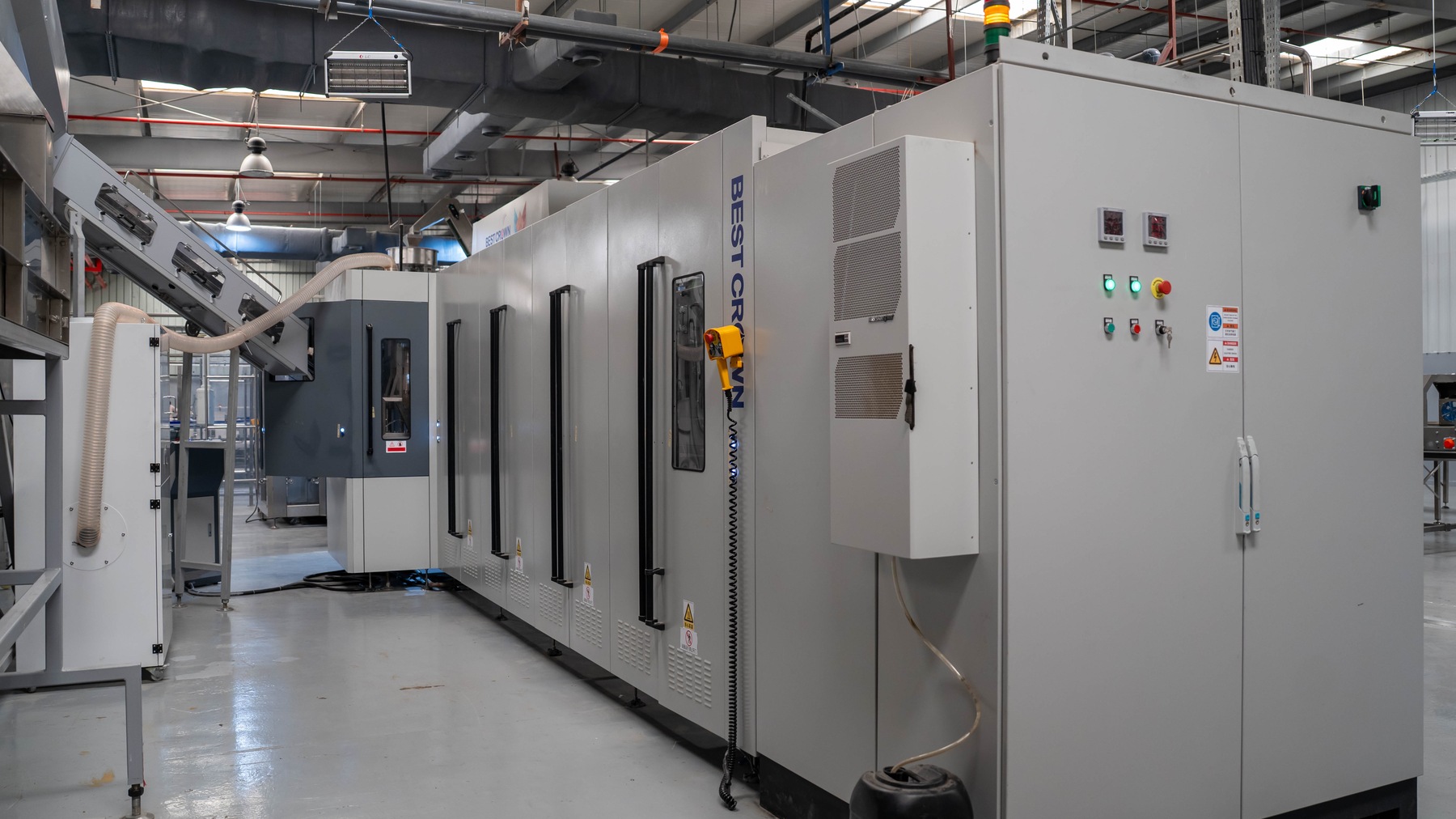
Project reference — automated preform feeding and blow molding line.
Orderly orientation and stable transfer support the required blow-molding rhythm. Feeding, buffering and transfer conditions must be coordinated with the connected blow-molding system.
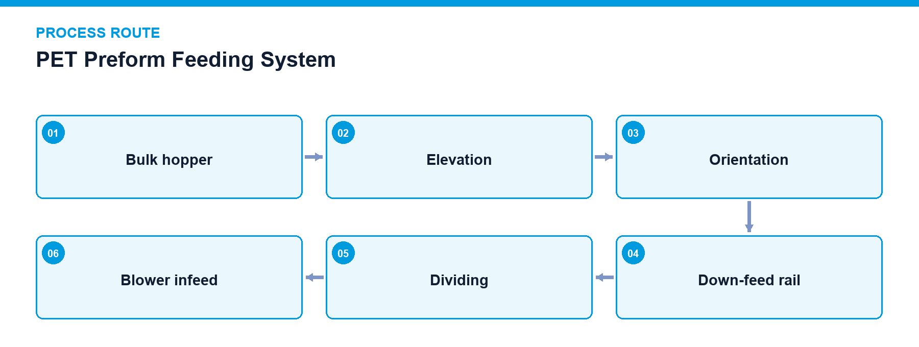
The preform feeding system receives bulk preforms, elevates and orients them, and delivers them continuously into the heating rails of the blow molding machine. Beyond simple material transport, the system manages preform orientation, rail stock levels, feeding rhythm, and recovery management following abnormal stoppages.
A typical feeding line comprises a storage hopper, an elevation conveyor, a sorting mechanism, and down-feed rails. When storage rails at the blow molder inlet indicate low levels, replenishment is requested; when upper limits are reached, elevation pauses. Jamming, reversed preforms, or rail congestion trigger controlled halts without exerting excessive crushing forces on the preforms.
Hopper Capacity: Designed according to preform consumption rates and manual or automated refilling intervals to prevent frequent reloading or excessive material compaction.
Elevation Transport: Belt or slat conveyors elevate preforms to the sorting height while interlocking with level detection sensors.
Orientation Mechanism: Utilizes neck support rings and center-of-gravity differentials to establish uniform upward neck orientation.
Down-Feed Rail: Maintains a continuous single-file queue while preventing preform inversion, overlapping, or jamming.
Level Control: High and low-level sensors regulate elevator operation, sorting units, and blow molder feed requests.
Changeover Provisions: Adjusts guide rails, spacing, and quick-change components when preform length, support ring, or neck finish specifications change.
Scroll horizontally to see all table columns.
| Component | Function |
|---|---|
| Storage Hopper | Receives bulk preforms from circulation containers and establishes upstream supply buffering |
| Preform Elevator | Elevates preforms to the operating height of the sorting unit |
| Sorting Unit | Orients preforms into vertical neck-up postures using neck support rings and dimensional differentials |
| Down-Feed Rails | Transports aligned preforms continuously along guide rails matching the neck finish |
| Dividing and Detection Unit | Feeds preforms individually according to machine rhythm while detecting missing, reversed, or jammed preforms |
Preform Elevation and Sorting: Track high and low levels coordinate elevator and sorter operation.
Rail Feeding: Maintains continuous single-file preform delivery to the machine inlet.
Level Interlocking: Automatically suspends elevation when rails reach capacity and resumes upon replenishment requests.
Jam and Abnormality Detection: Monitors for inversions, blockages, or missing preforms to prevent downstream feeding errors.
Downstream Coordination: Halts feeding operations immediately when downstream blow molding equipment stops.
Track high and low-level control logic
Elevator and blow molding machine operational interlocks
Jammed, reversed, and missing preform detection
Downstream stop response integration
Safety cover and maintenance mode interlocks
Regularly clean hoppers, elevation belts, rollers, and rails to prevent dust and debris from entering heating and blowing zones.
Establish safety barriers and maintenance modes around jam-clearing and manual replenishment points.
Implement inspection protocols to identify and isolate scratched, deformed, or contaminated preforms during incoming and feeding stages.
Preform temperature detection and defect rejection units
Automated hopper replenishment systems
Enclosed acoustic and protective guarding
Project reference only — not a standard specification.
Scroll horizontally to see all table columns.
| Application / Project Item | Configuration / Specifications | Usage Boundary |
|---|---|---|
| 10,000 BPH Water & CSD Projects | Hopper elevation, automatic orientation, rail feeding, and bin-level interlocking | Standard multi-project preform feeding architecture |
| 48,000 BPH CSD Blow-Fill-Seal Line | High-speed preform feeding integration matched to 24-cavity rotary blow molder | Project system configuration |
Optical level sensors coordinate elevator start and stop cycles, while mechanical guide profiles and spacing selectors prevent preform overlapping and excessive accumulation pressure.
Guide rails, orientation components, and spacing mechanisms must be adjusted or replaced using quick-change tooling matching the new neck finish and preform dimensions.
Provide your preform specifications, line speed requirements, and plant layout constraints to receive an optimized preform feeding system configuration.
Discuss your project