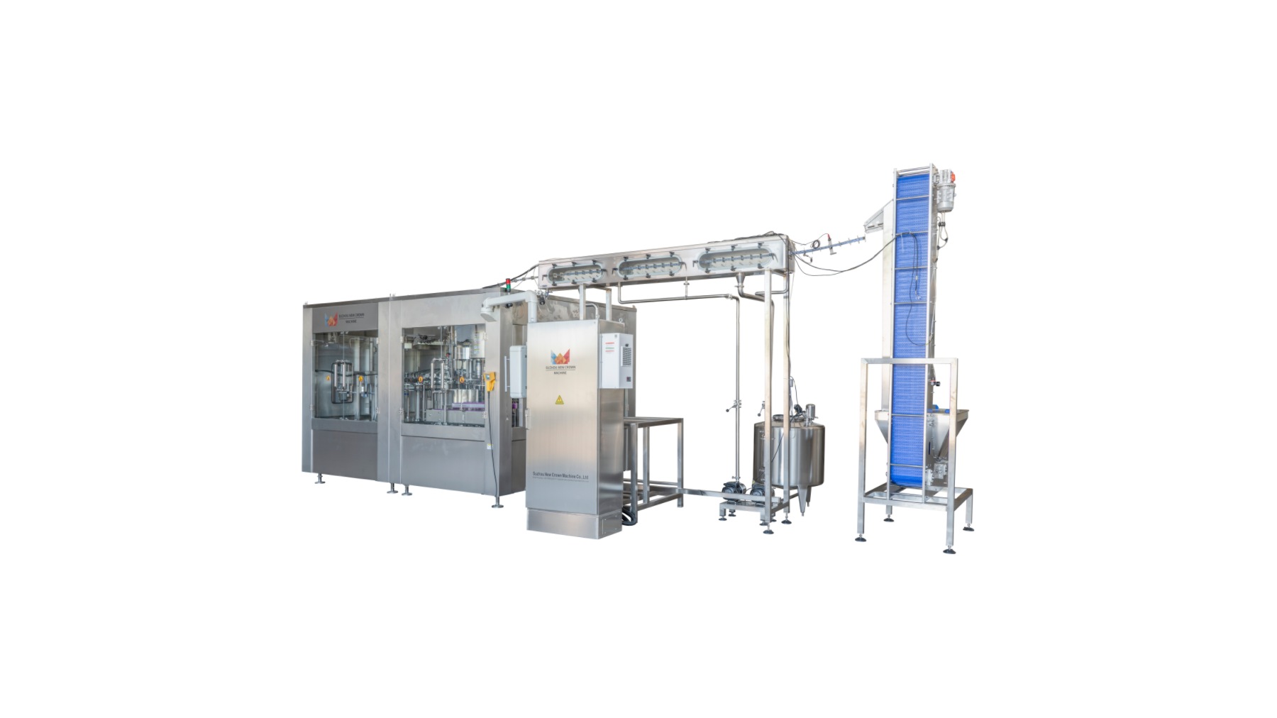
P25 / Beverage Filling Systems
Hot Filling System
A hot filling system transfers thermally sterilized beverages at controlled high temperatures into heat-resistant containers, immediately executing capping followed by container inversion and multi-zone water spray cooling. Integrating continuous thermal processing, thermal buffer holding, specializ
Scope of Application
| Application Route | Target Products & Containers |
|---|---|
| PET Juice Beverages | Heat-resistant PET bottles for fruit and vegetable juices. |
| Tea Beverages | Still and flavored tea drinks processed via hot filling routes. |
| Functional Drinks | Non-carbonated functional and vitamin-enhanced beverages. |
| Other Non-Carbonated Drinks | Applicable non-carbonated beverages suited to hot fill processing. |
Process Path
| Sequence | Process Stage |
|---|---|
| 01 | Thermally treated and verified product supply. |
| 02 | Thermal buffer holding and fluid delivery. |
| 03 | Container rinsing or pre-treatment. |
| 04 | Hot liquid quantitative filling. |
| 05 | Screw capping. |
| 06 | Container inversion. |
| 07 | Multi-zone water spray cooling. |
System Design and Operating Logic
The hot filling system functions as part of a continuous temperature process. After liquid products reach project-specified conditions via plate heat treatment, unnecessary temperature drop is restricted between thermal buffer loops and filling machines. Filling, capping, inversion, and spray cooling must operate in synchronized continuous rhythm.
Hot filling monoblocks integrate container rinsing, filling, and capping into a single rotary machine. Filling permission is granted once product temperatures enter allowable thresholds; lower product temperatures or upstream recirculation conditions prohibit normal filling entry. Following sealing, container inversion ensures hot liquid contacts the inner neck and cap sealing surfaces before entering multi-zone spray cooling tunnels. Short production stoppages require managing fluid dwell time in supply pipes, filling bowls, and valve bodies, executing recirculation, drainage, or re-sterilization according to stoppage duration.
Key Design Details
| Design Element | Technical Specification |
|---|---|
| Thermal Supply Loop | Minimizes temperature loss between thermal treatment outlets and filling machines while monitoring temperature and liquid levels. |
| Container Rinsing & Pre-Treatment | Determines rinsing media, container heat resistance, and neck finish conditions based on hygienic routes. |
| Hot Filling Valves | Adapts valve bodies, product bowls, and supply loops to hot liquid products and CIP cleaning requirements. |
| Capping and Sealing | Executes rapid capping following filling while controlling capping head statuses and missing-cap interlocks. |
| Short-Stop Management | Regulates continued operation, recirculation, or re-preparation based on product temperature and dwell time. |
| Inversion and Cooling | Establishes container inversion contact duration, spray zone temperatures, and discharge temperature thresholds. |
Major Components and Functions
| Component | Primary Function |
|---|---|
| Thermal Supply Loop | Restricts temperature loss between thermal treatment equipment and filling machines. |
| Filling Carousel & Valves | Performs quantitative liquid dosing at specified product temperatures. |
| Cap Supply & Capping Units | Seals containers immediately following filling operations. |
| CIP Dummy Cups & Recirculation | Connects product bowls, filling valves, and piping manifolds to CIP cleaning systems. |
| Cooling Interface | Transfers sealed hot products continuously to inversion and cooling equipment. |
Operation and Control
Temperature Permissive: Grants filling permissions based on product temperature thresholds.
Level & Flow Regulation: Manages supply tank liquid levels and product flow rates.
Safety Interlocks: Enforces missing-bottle protection for filling and cap feeding.
Short-Stop Control: Manages recirculation and temperature states during production pauses.
Downstream Linkage: Coordinates operation with container inversion and spray cooling equipment.
Cleaning, Maintenance, and Changeover
CIP Integration: Product bowls, supply piping, filling valves, and dummy cup loops are integrated into CIP cleaning programs.
Component Maintenance: High-temperature seals, moving valve components, and capping heads are maintained according to operating thermal conditions.
System Recovery: Product grade changes or extended stoppages require verifying fluid recirculation, drainage, and re-heating procedures.
Engineering Interfaces
| Interface Category | Connected System Elements |
|---|---|
| Upstream Interface | Continuous thermal treatment units and thermal buffer tanks. |
| Package Supply | Container rinsing units and cap feeding systems. |
| Utility Interfaces | CIP cleaning systems, cooling water, compressed air, and steam/electrical utilities. |
| Downstream Interface | Container inversion machines and multi-zone spray cooling tunnels. |
Project Definition Inputs
Product formulation and thermal treatment conditions.
Filling temperature requirements.
Product viscosity and pulp content.
Container heat resistance specifications.
Cap specifications.
Target bottle speed (BPH).
Container inversion contact duration.
Cooling discharge temperature requirements.
Options and Integration Items
Selection of specialized filling valves and supply modes based on fluid characteristics.
Online temperature recording, low-temperature recirculation, and short-stop event management.
Synchronization with container inversion, spray cooling, air drying, and labeling stations.
Project Configuration Example
| Project Description | Configuration / Operating Conditions | Technical Scope |
|---|---|---|
| 500 mL PET Juice Hot Fill Line | 18-18-6 rinser-filler-capper monoblock; design capacity 5,000 BPH | Integrated with 3 t/h product treatment, container inversion, and spray cooling |
Project Reference
Project Reference Only — Not a Standard Specification
- Project Configuration: 5,000 BPH, 500 mL PET juice hot fill line utilizing rinser-filler-capper configuration Model RCGF18-18-6 (18 rinsing heads, 18 filling valves, 6 capping heads), design capacity 5,000 BPH.
- Rinsing Stations: 3 rinsing positions.
- Utility Parameters: Rinsing water supply pressure 0.18–0.25 MPa, consumption approx. 1,300 kg/h.
- Upstream & Downstream Integration: 3,000 LPH product treatment system, container inversion, multi-zone spray cooling, air drying, sleeve labeling, and film packaging systems.
- Utility Records: Compressed air supply pressure 0.5 MPa, consumption approx. 0.5 m³/min.
- Main Drive & Dimensions: Main drive power 7.5 kW, weight approx. 4,000 kg, dimensions approx. 2300 × 1600 × 2100 mm.

Frequently Asked Questions
Q: Why is container inversion required after hot filling?
A: Inversion ensures that the hot liquid contacts the inner neck finish and cap interior surfaces, achieving thermal sanitization of the sealing area.
Q: How are short production stoppages managed on hot filling lines?
A: Stoppage management regulates fluid dwell time in piping and bowls, executing recirculation, drainage, or temperature re-establishment depending on stoppage duration.
Q: Can standard PET bottles be utilized on hot filling lines?
A: No. Hot filling requires specialized heat-resistant PET containers capable of withstanding elevated liquid temperatures and subsequent cooling contraction.
Call to Action
Consult our engineering team to integrate a reliable hot filling system configured for your juice, tea, or functional beverage production requirements.