Application scope
- Filling machine open exterior surfaces
- Isolator chamber internal spaces
- Container and cap handling zones

Pretreatment and Process Systems
Within aseptic or ultra-clean bottling installations, COP and SOP are utilized for the cleaning and sanitization or sterilization of isolator chambers and open equipment surfaces, while CIP and SIP manage closed product-contact circuits.
Project fit snapshot
Suitability depends on the product, container, output, hygienic route and connected equipment. Conditions outside the published scope require engineering review.
Technical content: fourth editionProject records shown below are project-specific references, not standard specifications.
Within aseptic or ultra-clean bottling installations, COP and SOP are utilized for the cleaning and sanitization or sterilization of isolator chambers and open equipment surfaces, while CIP and SIP manage closed product-contact circuits. These methods constitute an integrated equipment hygiene treatment framework, but their operational scopes and programs are mutually exclusive.
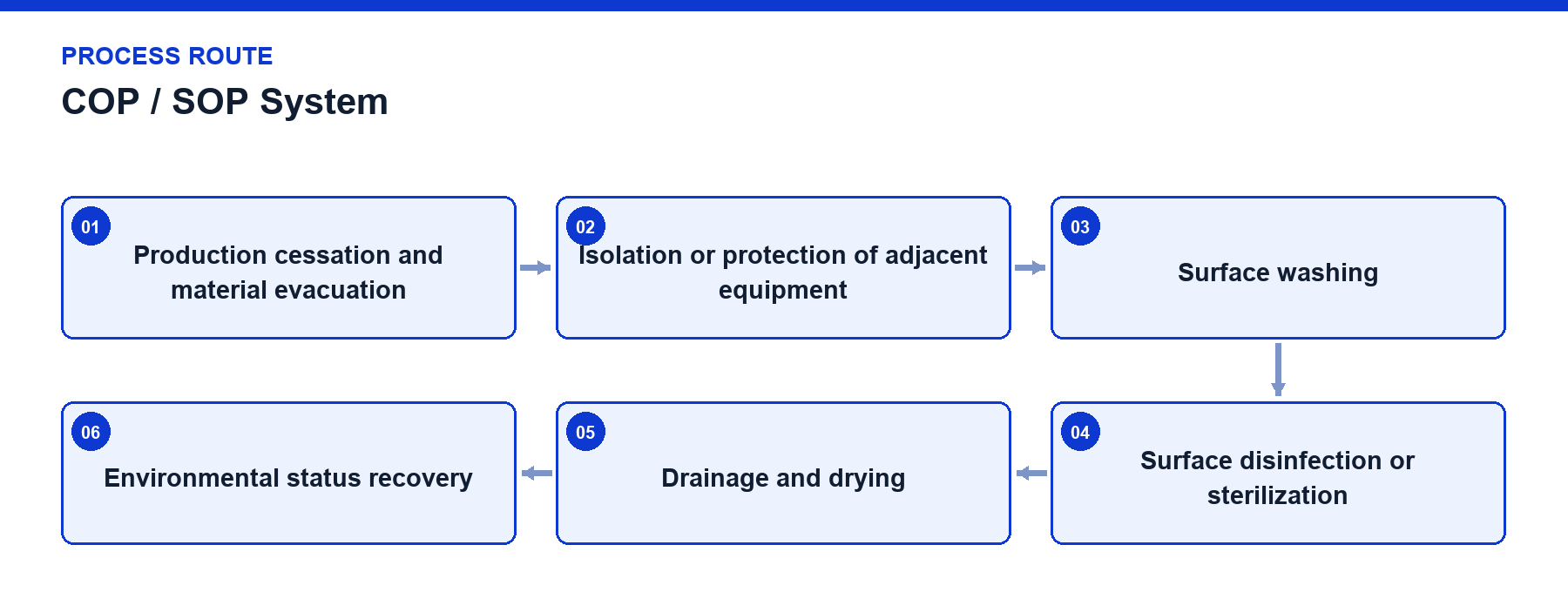
Equipment surface treatment route comprises:
01 Production cessation and material evacuation -> 02 Isolation or protection of adjacent equipment -> 03 Surface washing -> 04 Surface disinfection or sterilization -> 05 Drainage and drying -> 06 Environmental status recovery.
COP and SOP target isolator enclosures, exposed equipment structures, and open surfaces. COP removes visible residues and deposits, while SOP performs disinfection or sterilization on designated surfaces and spaces upon completion of cleaning; closed product piping, valve assemblies, and filling valves are addressed separately by CIP and SIP.
The primary engineering challenge in open surface treatment involves achieving comprehensive coverage, effective drainage, and rigorous isolation. Spray media must reach inner door panels, protective guards, filling turntables, and potential liquid pooling areas while avoiding mechanical drive tracks, electrical components, and blow-molding side structures unsuited for direct media contact.
Program completion does not immediately render equipment ready for production. The system must execute residual liquid discharge, controlled drying, clean air environment recovery, door status verification, and key environmental parameter checks before re-establishing production operating permits.
Treatment Boundaries: Equipment diagrams and control programs clearly delineate open surfaces, closed product circuits, package contact zones, and non-treated areas.
Spray Coverage: Nozzle positioning, spray angles, and flow rates are engineered around shadow zones, turntable interiors, and surfaces inaccessible to manual cleaning following maintenance.
Media Isolation: Blow-molding sections, mechanical drive tracks, electrical components, and adjacent equipment are partitioned or shielded according to structural and material criteria.
Material Compatibility: Compatibility between cleaning or disinfecting media and metals, plastics, observation windows, elastomeric seals, and lubricants is verified per project.
Drainage Capacity: Base plates, diversion channels, and drain ports prevent the formation of stagnant liquid pockets or unobservable pooling zones following treatment.
Drying and Recovery: Post-drainage environmental conditions are restored utilizing controlled airflow and specified waiting stages.
Door and Mode Interlocks: Opening doors and initiating production actions are restricted during active treatment; maintenance door openings trigger recovery procedures scaled to the affected zone.
Process Logging: Programs, operating phases, durations, temperatures, media statuses, and interrupt events are recorded for project validation and batch traceability.
Scroll horizontally to see all table columns.
| Component | Function |
|---|---|
| Cleaning and Spray Circuit | Delivers cleaning media to specified exterior surfaces or enclosure zones |
| Isolation and Protection Structure | Defines treatment boundaries and shields components unsuited for media contact |
| Drainage and Drying System | Removes residual liquids and establishes conditions for production recovery |
| Program and Door Status Interlocks | Control cleaning sequences, isolator doors, and equipment operating modes |
Scroll horizontally to see all table columns.
| Step | Operation | Control and Verification |
|---|---|---|
| 1 | Production Cessation and Evacuation | Confirm product clearance, equipment standstill, and target treatment zone isolation. |
| 2 | Execute COP | Complete pre-rinse, washing, rinsing, and drainage stages in established sequence. |
| 3 | Confirm Cleanliness Status | Inspect program results and anomaly logs; re-execute treatment if required. |
| 4 | Execute SOP | Deliver project-specified treatment media to designated surfaces or spaces. |
| 5 | Drainage and Drying | Maintain enclosure isolation while completing residual liquid removal and controlled drying. |
| 6 | Restore Production Permits | Verify that doors, airflow conditions, media statuses, and equipment modes are fully permitted. |
COP first washes isolator chambers and open equipment surfaces to remove production residues and soils; following washing, rinsing, and drainage, SOP executes disinfection or sterilization on designated surfaces and spaces per project specifications. Closed material circuits are processed via CIP and SIP. Within aseptic stretch-blow-fill-rotary systems, when filling zones undergo COP or SOP, the blow-molding side must be isolated from treatment media to prevent ingress into mechanical tracks and sensitive assemblies. Upon program completion, the system executes drainage, drying, and environmental recovery in a predetermined sequence.
Isolation door and maintenance door status detection.
Interlocks between treatment programs and production operating permits.
Sequential control governing spray, drainage, and drying phases.
Controlled system recovery following abnormal program interruptions.
Nozzle clogging, angular deviation, and scale accumulation on diversion structures alter spray coverage and must be incorporated into routine inspections.
Hoses, cabling, or components added during maintenance must not create new spray shadow zones or liquid pooling points.
Isolator seals, door locking mechanisms, and drain port statuses directly influence program boundaries and recovery timelines.
Treatment media concentrations, temperatures, exposure durations, and contact times are established based on specific equipment, materials, and validation protocols.
Project reference only — not a standard specification.
Scroll horizontally to see all table columns.
| Project Configuration | Parameter / Equipment Item | Configured Value / Description | Usage Boundary |
|---|---|---|---|
| Aseptic Blow-Fill-Rotary Line | Hygiene Architecture | Integrated isolator spray manifolds, door-interlocked SOP routines, and staged dry-air recovery cycles | Project specific engineering |
COP and SOP operate in parallel with or independently of CIP/SIP, focusing exclusively on external surfaces, isolator interiors, and non-product-contact zones, whereas CIP/SIP covers internal product-contact pathways.
Automated COP/SOP covers routine cleaning and sanitization of designated enclosed zones, but periodic manual inspection and specialized detailing may be required based on facility validation protocols.
Consult our aseptic packaging specialists to integrate a COP/SOP hygiene management system into your advanced filling line.
Discuss your project