Application scope
- Bottled drinking water preparation
- Carbonated beverage formulation water
- Juice and tea beverage blending water

Pretreatment and Process Systems
The Water Treatment System is engineered to transform raw water, formulation ingredients, and process utilities into high-purity water meeting strict bottling and processing requirements, while establishing integrated cleaning and sanitation auxiliary loops.
Project fit snapshot
Suitability depends on the product, container, output, hygienic route and connected equipment. Conditions outside the published scope require engineering review.
Technical content: fourth editionProject records shown below are project-specific references, not standard specifications.
The Water Treatment System is engineered to transform raw water, formulation ingredients, and process utilities into high-purity water meeting strict bottling and processing requirements, while establishing integrated cleaning and sanitation auxiliary loops. Rather than relying on a fixed equipment list, the system architecture is dynamically determined by raw water analysis, target water quality profiles, and peak production flow rates to establish tailored multi-stage filtration, membrane separation, terminal treatment, and storage buffering solutions.
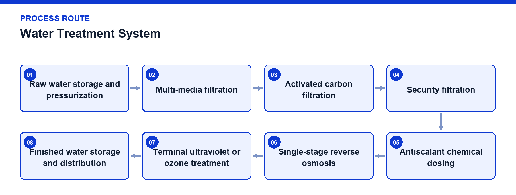
Reverse osmosis process configuration comprises:
01 Raw water storage and pressurization -> 02 Multi-media filtration -> 03 Activated carbon filtration -> 04 Security filtration -> 05 Antiscalant chemical dosing -> 06 Single-stage reverse osmosis -> 07 Terminal ultraviolet or ozone treatment -> 08 Finished water storage and distribution.
Water treatment engineering begins by matching water sources with target applications rather than pre-determining equipment models. Capacities for raw water pumps, filtration units, membrane systems, terminal disinfection, and storage tanks must be balanced against aggregate water demands, which encompass product water as well as batching, Clean-In-Place (CIP), equipment rinsing, and production changeover peak requirements.
Typical project routes utilize multi-media filtration for suspended solid interception, activated carbon filtration for residual chlorine, odor, and partial organic removal, and security filtration as final particulate protection prior to high-pressure pumping. The reverse osmosis main unit subsequently separates incoming water into purified permeate and concentrated reject streams.
Terminal ultraviolet disinfection, ozone treatment, and finished water storage are not interchangeable fixed combinations; their selection depends on product type, storage duration, downstream hygienic routing, and acceptance criteria, operating under start-stop interlocking logic linked with actual water flow, tank levels, and consuming equipment status.
Raw Water Conditions: Evaluations originate from comprehensive water analysis, verifying turbidity, hardness, residual chlorine, salinity, and potential membrane foulants.
Pretreatment Throughput: Sand filtration, activated carbon filtration, and security filtration are sized according to maximum instantaneous feed water flow rather than nominal final permeate volume.
Membrane Mass Balance: Feed, permeate, and concentrate flow rates are individually calculated, reserving operational margins for startup, flushing, and short-term hydraulic fluctuations.
Membrane Protection: High-pressure pump water shortage, inlet pressure, differential filtration pressure, and antiscalant dosing status govern membrane system operational permits.
Water Quality Observation: Operational trends are monitored via pressure, flow, and permeate conductivity; final project acceptance is dictated by target application criteria.
Terminal Treatment: Ultraviolet or ozone units operate in coordination with actual water flow, executing controlled start-stop sequences upon water cessation, low tank levels, or downstream stoppage.
Storage Buffering: Finished water storage tanks absorb hydraulic rate discrepancies between continuous membrane permeate production and intermittent filling or blending consumption.
Hygiene and Drainage: Tank breathing, overflow, drainage, circulation, and cleaning interfaces are established during the preliminary equipment layout phase.
Scroll horizontally to see all table columns.
| Component | Function |
|---|---|
| Raw Water Pump | Delivers continuous flow and inlet pressure to pretreatment and membrane systems |
| Multi-Media Filter | Intercepts suspended solids and larger particles to reduce downstream filtration load |
| Activated Carbon Filter | Removes residual chlorine, odor, and partial organics while protecting downstream membrane elements |
| Security Filter | Captures fine particles immediately upstream of the high-pressure pump |
| Antiscalant Dosing Unit | Mitigates inorganic salt scaling risks on the membrane concentrate side |
| Reverse Osmosis Main Unit | Comprises high-pressure pumps, pressure vessels, membrane elements, and piping for desalting separation |
| Ultraviolet and Ozone Units | Execute terminal disinfection according to project routing requirements |
| Finished Water Tank and Delivery Pump | Buffer permeate production and water usage rhythms while supplying downstream equipment |
Scroll horizontally to see all table columns.
| Step | Operation | Control and Verification |
|---|---|---|
| 1 | Raw Water Storage and Pressurization | Low liquid level stops pumps; inlet pressure and available flow are verified. |
| 2 | Multi-Media and Carbon Filtration | Inlet/outlet pressure and running time are monitored; backwash or maintenance is executed per project conditions. |
| 3 | Security Filtration and Dosing | Abnormal pressure drops or chemical shortages restrict membrane stage startup. |
| 4 | Reverse Osmosis Separation | High-pressure pumps, stage pressures, permeate/concentrate flows, and permeate conductivity are monitored. |
| 5 | Terminal Treatment | Ultraviolet or ozone operation is linked with flow rate, liquid level, and downstream demand. |
| 6 | Finished Water Storage and Supply | High liquid level ceases permeate production; low liquid level restricts downstream withdrawal or triggers makeup requests. |
Raw water undergoes particulate and adsorption filtration to prevent suspended solids and residual chlorine from directly entering membrane modules. Water conditioned by security filtration is pressurized by high-pressure pumps into reverse osmosis membrane assemblies, separating into permeate and concentrate under transmembrane pressure differential. Permeate advances to terminal treatment and storage, while concentrate is managed through project-specific discharge or recovery schemes.
Filtration capacity, membrane feed volume, and final permeate output are distinct parameters. System design calculates pretreatment throughput, membrane recovery rates, production peak demands, cleaning water volumes, and storage buffering simultaneously, preventing situations where bottling lines are designed on bottle-per-hour metrics while water treatment is matched solely to nominal average flows.
Raw water low level, high-pressure pump water shortage, downstream tank high level, and filter differential pressure anomalies participate in start-stop interlocking.
Membrane operational status is observed through inlet pressure, stage pressure, permeate flow, concentrate flow, and permeate conductivity.
Ultraviolet and ozone units coordinate with actual water flow, halting ineffective operation or chemical dosing during water supply interruptions.
Filter backwashing and cartridge replacement intervals are determined by pressure drop and water quality trends rather than rigid calendar scheduling.
Activated carbon stages require careful management of chlorine breakthrough and microbial risks, with established procedures for shutdown, recovery, and prolonged idling.
Membrane flushing, chemical cleaning, and preservation protocols are defined by fouling tendencies and project technical agreements.
Finished water tanks, circulation piping, and downstream interfaces should avoid long-term stagnant areas and include dedicated drain, sampling, and cleaning connections.
Project reference only — not a standard specification.
Scroll horizontally to see all table columns.
| Project Configuration | Parameter / Equipment Item | Configured Value / Description | Usage Boundary |
|---|---|---|---|
| 10,000 BPH, 300 mL PET Bottled Water Line | Water Treatment Permeate Capacity | 6,000 LPH | Project configuration value |
| 10,000 BPH, 300 mL PET Bottled Water Line | Main Process Route | Sand filtration, activated carbon, security filtration, antiscalant dosing, single-stage RO, ultraviolet, ozone, storage tank | Project configuration |
| 10,000 BPH, 330 mL PET CSD Line | Water Treatment Permeate Capacity | 5,000 LPH | Project configuration value |
| 10,000 BPH, 330 mL PET CSD Line | Pretreatment Inlet Equipment | Raw water pump rated flow 10 m³/h | Does not equal final permeate flow |
| 10,000 BPH, 300 mL PET Bottled Water Line | Raw Water Pump | 12 m³/h, 3 kW | Project equipment schedule |
| 10,000 BPH, 300 mL PET Bottled Water Line | Sand and Carbon Filters | 12 m³/h each, vessel approximately Ø700×2300 mm, design pressure 0.4 MPa | Project equipment schedule |
| 10,000 BPH, 300 mL PET Bottled Water Line | Security Filter | 12 m³/h, 5 μm rating | Project equipment schedule |
| 10,000 BPH, 300 mL PET Bottled Water Line | Reverse Osmosis Membrane Array | 6 units of 8040 membrane elements; recorded recovery rate not less than 50% | Project specific record |
| 10,000 BPH, 300 mL PET Bottled Water Line | Terminal and Storage | 6 t/h ultraviolet unit, 30 g/h ozone generator, 6,000 L finished water tank | Project configuration |
| 10,000 BPH, 330 mL PET CSD Line | Pretreatment Line | Sand and carbon filters 10 m³/h each; security filter 5 μm rating | Project equipment schedule |
| 10,000 BPH, 330 mL PET CSD Line | Reverse Osmosis Membrane Array | 5 units of 8040 membrane elements; recorded recovery rate not less than 50% | Project specific record |
| 10,000 BPH, 330 mL PET CSD Line | Terminal and Storage | 5 t/h ultraviolet unit, 25 g/h ozone generator, 5,000 L finished water tank | Project configuration |
No. Water treatment system capacity is engineered to satisfy net product water requirements combined with peak demands for batching, CIP rinsing, equipment sanitization, and production transitions, rather than sharing a direct nominal equivalence with line speed.
No. Their configuration depends on product category, storage duration, downstream hygienic routing, and microbiological acceptance criteria, operating under start-stop interlocks tied to actual water flow.
Consult our engineering specialists with your raw water analysis and production parameters to establish a tailored water treatment system architecture.
Discuss your project