Application scope
- The application scope covers PET fruit juice hot-filling, tea beverage hot-filling, and other products requiring post-capping partitioned cooling.

Secondary Packaging and End of Line
The spray cooling tunnel cools hot-filled beverage containers through multi-zone circulating water sprays, gradually removing thermal energy to reach target exit temperatures while preventing prolonged high-temperature exposure.
Project fit snapshot
Suitability depends on the product, container, output, hygienic route and connected equipment. Conditions outside the published scope require engineering review.
Technical content: fourth editionProject records shown below are project-specific references, not standard specifications.
The spray cooling tunnel cools hot-filled beverage containers through multi-zone circulating water sprays, gradually removing thermal energy to reach target exit temperatures while preventing prolonged high-temperature exposure.
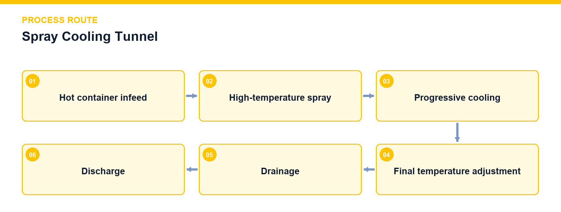
The spray cooling tunnel achieves step-by-step cooling for hot-filled products, limiting container high-temperature exposure and establishing proper exit conditions for drying, labeling, and packaging. While mechanically similar to the bottle warmer, thermal load direction, temperature zone layout, and process objectives differ. Sealed hot bottles pass through multiple spray zones where circulating water absorbs container and product heat before returning to water tanks for thermal regulation, cooling, or make-up water adjustment. Cooling speed balances product temperature, container heat resistance, deformation risks, and equipment length.
Scroll horizontally to see all table columns.
| Design Object | Technical Description |
|---|---|
| Zone Temperature Gradients | Step-by-step cooling across multiple spray zones to prevent excessive thermal differentials. |
| Circulating Water Circuit | Independent or connected zone water tanks, pumps, filters, and spray nozzles. |
| Cooling Source Interface | Connections for cooling water, chilled water, or plate heat exchangers based on thermal load. |
| Chain Speed and Dwell Time | Chain speed governing residence time, integrated with overall line speed coordination. |
| Exit Conditions | Exit temperature and surface moisture meeting air-drying, labeling, and packaging requirements. |
Scroll horizontally to see all table columns.
| Component | Function |
|---|---|
| Tunnel Housing and Slat Chain | Establish enclosed spray space and residence time. |
| Zoned Circulating Water Tanks | Maintain individual zone water temperatures. |
| Spray Pumps, Nozzles, and Filters | Ensure uniform spray coverage and circulating cleanliness. |
| Heat Exchange and Make-Up Systems | Remove absorbed heat and regulate water volume. |
| Temperature and Speed Controls | Coordinate zone settings and container dwell time. |
Operation and control encompass zone water temperature and circulating pump interlocks, transport speed and residence time control, water tank level protection, spray pressure or flow monitoring, and upstream/downstream jam status interlocking.
Cleaning and maintenance require regular cleaning and blowdown for circulating water, nozzles, filters, and tanks, ensuring drainage and inspection accessibility for equipment bottoms, slat chains, and guide rails, and maintaining calibretable and isolatable temperature sensors and heat exchange interfaces.
Scroll horizontally to see all table columns.
| Input Parameter | Description |
|---|---|
| Thermal Parameters | Infeed and target exit temperatures, product thermal properties. |
| Container & Speed | Container shape, volume, and target bottle speed. |
| Utilities & Limits | Allowable temperature gradient, cooling water conditions, and equipment length limits. |
Project reference only — not a standard specification.
Scroll horizontally to see all table columns.
| Project Description | Configuration / Parameter | Use Boundary |
|---|---|---|
| 5,000 BPH, 500 mL PET Juice Hot-Fill Line | Installed after bottle inverter and before air-drying/sleeving | Project Process Flow |
| 48,000 BPH CSD Line | Shared equipment logic where spray tunnels utilize zone and media routing for warming or cooling, subject to independent thermal load engineering | Project Engineering Record |
Multiple spray zones with progressive temperature steps reduce thermal differentials gradually, preventing container deformation or breakage.
While mechanical structures share similarities, thermal direction and zone configurations are engineered specifically for cooling or warming based on project thermal load requirements.
Engage our thermal engineering specialists to size and configure a spray cooling tunnel tailored to your hot-fill line capacity.
Discuss your project