Application scope
- PET Bottled Drinking Water: Packaged still drinking water in PET containers.
- Non-Carbonated Low-Viscosity Water: Low-viscosity still liquid water products.
Beverage Filling Systems
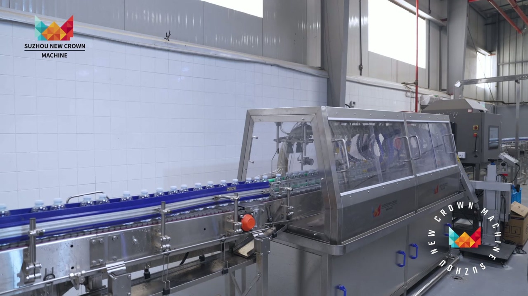
A bottled water filling system consolidates empty container rinsing, constant-level gravity filling for non-carbonated water, and magnetic torque screw capping into a single integrated rotary monoblock machine.
Project fit snapshot
Suitability depends on the product, container, output, hygienic route and connected equipment. Conditions outside the published scope require engineering review.
Technical content: fourth editionProject records shown below are project-specific references, not standard specifications.
A bottled water filling system consolidates empty container rinsing, constant-level gravity filling for non-carbonated water, and magnetic torque screw capping into a single integrated rotary monoblock machine. Operating with neck-handling or body-positioning mechanics, it coordinates seamlessly with raw water supply, closure feeding, and clean-in-place (CIP) circuits to ensure reliable, high-speed production of packaged still drinking water.
Project reference — PET bottled water filling monoblock.
Scroll horizontally to see all table columns.
| Application Route | Target Products & Containers |
|---|---|
| PET Bottled Drinking Water | Packaged still drinking water in PET containers. |
| Non-Carbonated Low-Viscosity Water | Low-viscosity still liquid water products. |
Scroll horizontally to see all table columns.
| Sequence | Process Stage |
|---|---|
| 01 | Empty container infeed. |
| 02 | Container inversion and rinsing. |
| 03 | Drip-drying and container reset. |
| 04 | Constant-level gravity filling. |
| 05 | Screw capping. |
| 06 | Finished bottle discharge. |
Bottled water filling focuses on stable liquid levels, low mechanical agitation, and continuous hygienic liquid supply. Empty containers entering rinsing carousels are inverted and rinsed before being transferred via starwheels to filling turrets; filling is immediately followed by capping to reduce the open exposure time of unsealed products.
Monoblock equipment utilizes constant-level gravity filling, regulated product bowl liquid levels, and filling valves connected via dummy cups to CIP recirculation loops. Missing-bottle protection, missing-cap detection, and downstream line blockages are integrated into machine safety interlocks.
Scroll horizontally to see all table columns.
| Design Element | Technical Specification |
|---|---|
| Rinsing Control | Manages container positioning, inversion, rinsing media, and drainage to prevent rinse liquid carryover into filling. |
| Starwheel Transfer | Coordinates smooth container transfer across rinsing, filling, and capping stations using neck and body guide elements. |
| Product Bowl Level | Regulates finished water supply based on liquid level signals to maintain stable filling valve inlet conditions. |
| Constant-Level Filling | Opens valves upon container positioning and closes when reaching design liquid levels. |
| Capping Operation | Manages cap storage, sorting, feeding, and capping head operation to ensure continuous closure application. |
| CIP Dummy Cups | Seals filling valve outlets during cleaning to form closed recirculation loops through bowls, valves, and piping. |
Scroll horizontally to see all table columns.
| Component | Primary Function |
|---|---|
| Infeed & Rinsing Carousel | Grips and inverts empty bottles to rinse internal surfaces or execute project-defined treatment. |
| Filling Turret | Performs constant-level gravity filling via product bowls and filling valves. |
| Cap Elevator & Sorter | Organizes bulk bottle caps into oriented continuous feed streams. |
| Magnetic Torque Capping Heads | Limits capping torque to prevent overtightening or loose sealing. |
| CIP Dummy Cups | Connects filling valve outlets to cleaning recirculation pathways. |
Liquid Level Control: Regulates product bowl levels during operation.
Safety Interlocks: Enforces no-bottle-no-rinse, no-bottle-no-fill, and missing-cap detection interlocks.
Line Synchronization: Manages infeed and discharge blockages to prevent container jams.
Operating Modes: Integrates production and CIP cleaning operating mode interlocks.
Component Maintenance: Rinsing clamps, filling valves, starwheels, and capping heads require cleaning and maintenance schedules tailored to container formats.
Post-Cleaning Verification: Cleaning completion requires verifying dummy cup reset, drainage completion, and production valve position recovery.
Hygienic Management: Bottle necks, closures, and finished water hygiene conditions are managed across integrated line boundaries.
Scroll horizontally to see all table columns.
| Interface Category | Connected System Elements |
|---|---|
| Upstream Interface | Air conveyors receiving bottles from blow molding or uncaser units, and treated product water supply. |
| Closure Feed | Cap elevators, automated sorters, and delivery chutes. |
| Utility Interfaces | CIP cleaning systems, rinse water supply, compressed air, and electrical power. |
| Downstream Interface | Capped bottle discharge starwheels, air conveyors, and packaging lines. |
Scroll horizontally to see all table columns.
| Project Description | Configuration / Operating Conditions | Technical Scope |
|---|---|---|
| 300 mL PET Bottled Water Line | 24-24-8 rinser-filler-capper monoblock; design capacity 10,000 BPH | Configured for specified project requirements |
Project Reference Only — Not a Standard Specification
- Project Configuration: 10,000 BPH, 300 mL PET bottled water line utilizing rinser-filler-capper configuration Model CGF24-24-8, design capacity 10,000 BPH.
- Utility Parameters: Rinsing water supply pressure 0.18–0.25 MPa, consumption approx. 2,500 kg/h.
- Container Range: Bottle diameter 50–100 mm, bottle height 150–320 mm (subject to format changeover part verification).
- Utility Records: Compressed air supply pressure 0.5 MPa, consumption approx. 0.8–1.0 m³/min.
- Main Drive & Dimensions: Main drive power 6 kW, weight approx. 4,000 kg.
Constant-level gravity filling valves utilize precise mechanical venting and regulated product bowl liquid levels to achieve uniform fill heights.
Magnetic torque capping heads provide adjustable torque limitation to ensure consistent sealing without thread damage.
Filling valve outlets are sealed with dedicated dummy cups, allowing cleaning solutions to circulate through product bowls, valves, and piping manifolds.
Consult our engineering team to specify a high-efficiency bottled water filling monoblock tailored to your plant capacity and container specifications.
Discuss your project