Application scope
- Single PET container transport
- Continuous beverage lines requiring minimized short-stop propagation
- Multi-device speed coordination

PET Blow Molding and Bottle Handling
PET bottle flow accumulation systems establish controlled accumulation and release between rate-sensitive adjacent packaging machines, absorbing short-term stoppages and speed fluctuations across the production line.
Project fit snapshot
Suitability depends on the product, container, output, hygienic route and connected equipment. Conditions outside the published scope require engineering review.
Technical content: fourth editionProject records shown below are project-specific references, not standard specifications.
PET bottle flow accumulation systems establish controlled accumulation and release between rate-sensitive adjacent packaging machines, absorbing short-term stoppages and speed fluctuations across the production line. Effective accumulation capacity is created through optimized conveyor lengths, multi-lane expansion, speed differentials, and permissible accumulation states.
Unbuffered short-term equipment stoppages severely degrade overall line efficiency. Controlled accumulation isolates upstream and downstream interruptions, allowing continuous operation of core processing units and minimizing thermal or mechanical shock across the line.
The primary objective of the bottle flow accumulation system is to absorb speed differentials during short-term stoppages without allowing uncontrolled container compaction on transport lines. Buffer lengths, container density, side-pressure limits, and absorption times are calculated based on actual bottle geometry and line speed.
Line integration requires the accumulation system to exchange operating states with upstream and downstream equipment. When downstream equipment slows or stops, the buffer progressively occupies zones, alerting upstream units to decelerate when capacity limits are approached. Upon recovery, containers are released sequentially from the discharge end upward, preventing surges and new blockages.
Target Buffer Time: Determines required effective capacity based on typical short-stop durations and line speeds.
Sectional Detection: Utilizes multiple occupancy sensors to evaluate buffer volume rather than relying solely on a single terminal full-line signal.
Speed Cascading: Adjusts conveyor section speeds gradually in response to buffer occupancy, limiting container impact forces.
Accumulation Pressure: Respects specific side-pressure thresholds for lightweight, irregular, or hot-filled containers.
Recovery Sequencing: Confirms downstream receiving readiness before releasing stored container flow from the discharge end upward.
Scroll horizontally to see all table columns.
| Component | Function |
|---|---|
| Accumulation Conveyor Sections | Provides calculable in-process container storage capacity |
| Guide and Diversion Mechanisms | Controls container flow transition between single-file and multi-lane configurations |
| Sectional Drives | Establishes buffering action through differential conveyor speeds |
| Bottle Flow Sensors | Monitors occupancy and congestion levels across buffer zones |
| Line Control System | Determines slowdown, stopping, and recovery sequences based on equipment states |
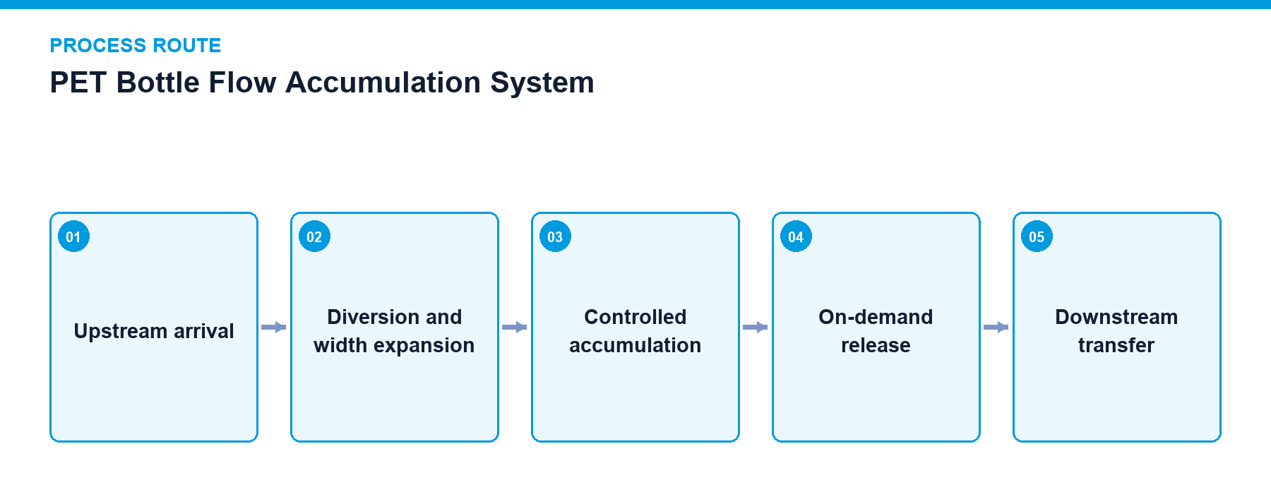
Buffer Intake: Receives incoming containers when downstream equipment slows down or stops.
Zone Accumulation: Progressively engages storage zones by reducing conveyor speeds or expanding multi-lane holding areas.
Upstream Modulation: Sends deceleration or stop signals to upstream units when buffer capacity approaches upper limits.
Controlled Recovery: Releases stored containers sequentially from the downstream end upward once downstream operations resume.
Alarm Monitoring: Detects and alerts operators to fallen bottles, blockages, or abnormal congestion.
Multi-zone buffer occupancy detection
Upstream and downstream speed cascading
Upstream deceleration and stop control upon full capacity
Tail-first sequential release upon recovery
Fallen bottle and congestion alarm integration
Maintain chain friction, lubrication, and guide rail conditions to ensure predictable accumulation pressures.
Provide accessible clearance points along buffer zones for clearing fallen or jammed containers.
Re-verify container density, guide rail widths, and sensor detection points following product changeovers.
Single-file delay buffering, multi-lane accumulation, or controlled side-by-side buffering
Automated strategy selection for deceleration, stopping, and recovery based on equipment status
Buffer occupancy visualization and short-stop event logging
Project reference only — not a standard specification.
Scroll horizontally to see all table columns.
| Application / Project Item | Configuration / Specifications | Usage Boundary |
|---|---|---|
| 24,000 BPH PET Water Project | Single, packed, and palletized conveying lines with independent accumulation and state handover | General system integration relationship |
Multi-zone optical sensors monitor buffer occupancy step-by-step; when storage approaches capacity limits, control signals progressively throttle or stop upstream production units.
Yes, accumulation pressure limits, side guide adjustments, and speed cascading are configured according to container weight and physical stability parameters.
Consult our line integration experts to evaluate your plant's buffering requirements and design a customized flow accumulation system.
Discuss your project